Radio Terminals
9967
MMU2 F 155
APU
1+1 XPIC
PFU1
0/1 2 3 4 5 6 7 8 9 10 11 12 13 14 15 16 17 18 19 20 21
AMM 20p
PFU2
FAU2
NPU
7
6
5
4
3
2
MMU2 F 155
APU
AMM 6p
1+1
XPIC
0 1
MMU2 F 155
MMU2 F 155
MMU2 F 155
1+1 XPIC
1+1 XPIC
1+1 XPIC
MMU2 F 155
MMU2 F 155
MMU2 F 155
MMU2 F 155
MMU2 F 155
MMU2 F 155
MMU2 F 155
MMU2 F 155
MMU2 F 155
MMU2 F 155
MMU2 F 155
MMU2 F 155
MMU2 F 155
MMU2 F 155
MMU2 F 155
PFU1
NPU
APU
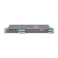
Figure 76 AMM 6p and AMM 20p in 1+1 XPIC configuration
Each pair of modems placed in adjacent BPI-2 sharing slots (for AMM 20p,
2&3 and 4&5, 6&7 and 8&9, etc.) is related to the same polarization of the
transmitted signal over the same wireless channel. Therefore, the front panel
XPIC cross-cable shall connect modems in alternate slots (2&4 and 3&5, etc.).
See Figure 77 on page 87.
9968
PFU2
FAU2
NPU
7
6
5
4
3
2
MMU2 F 155
APU
AMM 6p
1+1
XPIC
0 1
MMU2 F 155
MMU2 F 155
MMU2 F 155
Figure 77 XPIC cross-cable connections (A MM 6p)
4.6.3.2 Functional Description
The 1+1 XPIC configuration provides propagation protection and equipment
protection on the MMU, RAU and antenna when using both polarizations in
co-channel dual polarized (CCDP) mode of operation with XPIC.
87
4/1555-CSH 109 32/1-V1 Uen B 2007-09-14

 Loading...