Technical Description
6.2 PSU DC/DC Kit
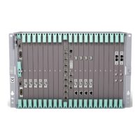
The PSU DC/DC kit is used for AMM 6p C/D or AMM 20p B, converting +24
V DC to –48 V DC with a maximum output power of 950 W. It consists of a
sub-rack (3U high), one or two Power Supply Units (PSU) and an FAU3. Two
PSUs are used for redundant power systems.
The +24 V DC external power supply is connected to the PSU front.
The sub-rack provides two –48 V DC connectors for PFU connection. Two
fused –48 V DC connectors for FAU1 connection are also available.
The sub-rack can be mounted in a standard 19" or metric rack or on a wall
using a dedicated mounting set.
E
A
R
T
H
GRO
U
N
D
I
N
G
FAU3
Fa
u
lt
P
o
w
e
r
-4
8
V
DC
P
o
w
e
r
A
la
r
m
-4
8V
D
C
O
U
T
A
B
00
01
-48VD
C
0V
-48VD
C
0V
3.15A
250V
3.15A
250V
-48VDC
0V
-48VDC
0V
+
PSU
Fault
Operation
Information
EC Bus
DC Out
DC In
+
PSU
Fault
Operation
Information
EC Bus
DC Out
DC In
FAU3
–48 V DC Out
(FAU1)
–48 V DC Out
(PFU1/PFU3)
–48 V DC Out
(PFU1/PFU3)
+24 V DC In
PSU
Fan alarm
(NPU1 B)
8261
Figure 95 PSU DC/DC kit
6.2.1 Cooling
Forced air-cooling is always required and provided by FAU3, which holds two
internal fans. It is power supplied by an internal pre-assembled cable connected
to the front. A connector for alarm export to the NPU1 B is also available.
128
12/221 02-CSH 109 32/1-V1 Uen A 2008-03-14

 Loading...