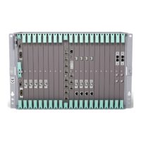
Basic Node
P
F
U
1
M
M
U
2
4
-
3
4
M
M
U
2
B
4
-
3
4
M
M
U
2
B
4
-
3
4
LT
U
1
6x
2
LTU
155e/o
NPU 8x2
-48V
Power
A
-48V
F
A
N
U
N
IT
Power B
Alarm B
Alarm A
Fault
Power
PFU
FAU
Air Guide Plate
Cable Shelf
10070
NPU1 B
NPU
Figure 14 AMM 20p B
3.2.3.1 Power Supply
AMM 20p is power supplied by –48 V DC, connected to the PFU1 or via an
Interface Connection Field (ICF1). The power is distributed from the PFU1 to
the plug-in units, via the power bus in the backplane of the subrack.
The power system is made redundant using two PFU1s, utilizing the redundant
power bus.
The PSU DC/DC kit enables connection to +24 V DC power supply, see Section
6.2 on page 128. The ICF1 is not used in this installation alternative.
15
12/221 02-CSH 109 32/1-V1 Uen A 2008-03-14

 Loading...