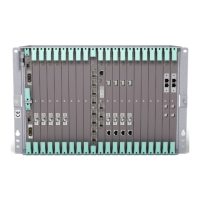
Basic Node
3.13 MINI-LINK E Co-siting
A SMU2 can be fitted in an AMM 2p B, AMM 6p C/D or AMM 20p B to interface
MINI-LINK E equipment on the same site. The following interfaces are provided:
• 1xE3 + 1xE1
• 1xE2 or 2xE2
• 2xE1
• 2xE0 (2x64 kbit/s) used for IP DCN
• O&M (V.24) access server
E
R
IC
S
S
O
N
SMU2
O&M
E3:3A
E2:3B-3C
E1:2A-2B
DIG SC:1A-1B
Fault
Pow
er
BR
E3/
2xE2
2xE0
O&M
SMU2
2xE1
6728
Figure 52 SMU2
All the traffic capacities are multiplexed/demultiplexed to nxE1 for connection
to the TDM bus.
SMU2
2xE0
2xE1, 1xE2, 2xE2 or 1xE3 + 1xE1
MINI-LINK E
2xE1 to 17xE1
7469
MINI-LINK TN
TDM Bus
Figure 53 MINI-LINK E co-siting
65
12/221 02-CSH 109 32/1-V1 Uen A 2008-03-14

 Loading...