Chapter 2
All signal connections are made via the rear panel. A typical rear panel is shown in
Figure 2.5. Full technical specifications for the connections are given in Annex B.
The Receiver provides a flexible Transport Stream input interface. The status
information appropriate to each input type is available to the User via the User
Interface, and also via the remote control interfaces.
ASI/HD-SDI/SD-
SDI OUT 1-3
TECHNICAL
EARTH
AC POWER
IP OUT 1-2
RF IN 1-4
CVBS
ALARM
CONTROL
1-2
SI INPUT
RX8200
Sample configuration
with: Satellite input,
frame sync, HD video
output, IP Transport
Stream output and 2x
Audio output modules
installed.
RX8310
RX8315
RX8320
RX8330
AUDIO OUT (1)
1-2
INPUT MODULE
AUDIO OUT (2)
3-4
COMPONENT
VIDEO
FRAME
SYNC
ETHERNET 1-2
TECHNICAL
EARTH
ASI OUT 1-2
CVBS
LARM ASI INPUT
AC POWER
RF IN 1-4 AUDIO OUT (1)
1-2
IP OUT 1-2
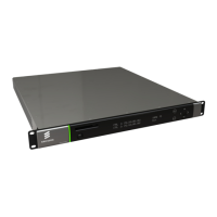
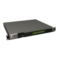
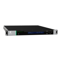
Figure 2.5 Rear Panels (RX8200, RX8310, RX8315, RX8320 and RX8330)
2.7.2 RF IN Connector (RX8200 and RX8320 only)
Up to four RF inputs connect the L-band output of a
suitable Low-Noise Block down-converter (LNB) to the
unit either directly or via a suitable attenuator.
The RF inputs may also be used to supply DC power to
the LNB, if required.
RF IN 1/2/3/4
EN/LZT 790 0005 R1A
2-10

 Loading...