142 SIERRA ST., EL SEGUNDO, CA 90245 USA (310)322-2136 FAX (310)322-8127 www.ESE-WEB.com
Page 1 of 22
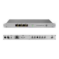
ES-102 GPS BASED
TIME CODE GENERATOR / MASTER CLOCK
OPERATION AND MAINTENANCE MANUAL
The ES-102 is a GPS Master Clock/Time Code Generator. The unit receives accurate time and date information from
Global Positioning System satellites and supplies this data to the user in the form of four (4) different types of time
code (SMPTE/EBU, ASCII, TC89 and TC90) and a front panel six-digit display (.56” yellow LEDs). Two (2) One Pulse
Per Second outputs and a GPS “Lock” output are also available. A twelve-channel receiver is employed that is
capable of tracking up to twelve (12) satellites simultaneously, although reception of only one is required for time data
to be output.
Several options are available that allow the unit to meet most any requirement asked from a Master Clock or Time
Code Generator. These options are described in the “OPTIONS” section.
INSTALLATION & OPERATION
The basic installation of the ES-102 is nearly as simple as connecting the Antenna Cable and 117 VAC to the unit,
and allowing the unit to "lock" onto GPS. However, after any "bench" testing is complete, the most important concern
is to mount the Antenna and route the cable according to the instructions provided on page 7.
All other connections between the ES-102 and other equipment should be made by a qualified technician or engineer.
The technician or engineer should be familiar with each piece of equipment being interfaced with the ES-102. Please
refer to the descriptions and specifications for details concerning the various Standard Features, Setup Features and
Options. Consult the manufacturer of the equipment or the ESE factory if assistance is required.
A lithium coin cell battery maintains the settings of the GPS receiver during periods without power. The battery is
capable of maintaining the settings for up to four years. If the receiver needs re-initialization, refer to the master clock
software program descriptions on page 11.
STANDARD FEATURES
Power Supply
The ES-102 is equipped with an internal Power Supply. The Power Supply requires 117 VAC via the 3-wire line cord.
Display
The front-panel contains a single green LED that indicates if the unit is "Locked" to GPS. When locked to GPS, the
LED remains lit. Prior to lock or when lock is lost, the LED blinks at a 1 Hz rate. The ES-102 also has a six-digit .56”
high yellow LED display.
Outputs
The rear-panel of the ES-102 provides access to the time codes, 1PPS and GPS Lock outputs via XLR, BNC and
DB-9 connectors. Please refer to the "Rear Panel DB-9 Connector Pin Designations" and "Specifications" for more
details.
EBU: The ES-102 can have an EBU Time Code output specified. The EBU Time Code Output is accessible
via an XLR connector. Accuracy of the EBU is +/- 400 mS and can be synchronized to a video source
via the "Video In" BNC connector. The EBU time code is automatically “re-synched” to GPS at
2:00:00 AM. EBU (European Broadcasting Union) is used predominantly in Europe in the TV, Cable
and Video industries.
SMPTE: The ES-102 can have a SMPTE Time Code output specified. The SMPTE Time Code Output is
accessible via an XLR connector. Accuracy of the SMPTE is +/- 400 mS and can be synchronized to
a video source via the "Video In" BNC connector. The SMPTE time code is automatically “re-
synched” to GPS at 2:00:00 AM. SMPTE (Society of Motion Picture and Television Engineers) is
used predominantly in the TV, Cable and Video industries. The SMPTE User Bits are, from high to
low, as follows: 1OY-X-Y-X-10M/10D-M-D-X. When Julian Day of Year is used, the SMPTE User Bits
are as follows: X-X-X-X-X-100D-10D-D.
Drop Frame: Unless otherwise specified, the unit is set to provide "Drop Frame" SMPTE Time Code. If
non-Drop Frame SMPTE is desired, turn “ON” the “NDF” DIP switch (switch #7 on the
ES-101 logic board).