ESI RF BRIDGE User Guide DRAFT, rev 4
www.elec-solutions.com © 2013 Electronic Solutions, Inc. Page 2 of 13
ESI RF Bridge — Factory Defaults
Observe the ESI RF Bridge LED for initialization during power-up:
9 Yellow, 7 Blue (Beta)
Flip position when using RQ
NOTE: RTS/CTS (hardware flow control) is not available for Beta versions of the ESI RF Bridge but will be
supported in the Production release.
Setup
Hardware Requirements
ESI RF Bridge (with 5 volt DC power supply and USB to Mini-B cable).
PC computer or laptop with DB-9 style (DE-9) serial port, or USB port for a USB Serial Adaptor cable.
o Terminal program for the PC, such as HyperTerminal or Tera Term.
o RS-232 male to female cable or USB Serial Adaptor cable (USB with DB-9 style male connector).
OPTIONAL: SUITE remote, to provide an additional method of motor administration and control, in
addition to the automation system.
Terminal Emulator Settings
Serial Port Settings: 9600 baud, 8 bits, 1 stop bit, no parity
Flow Control: Software Xon/Xoff
Local Echo: off
Do not insert a linefeed after CR.
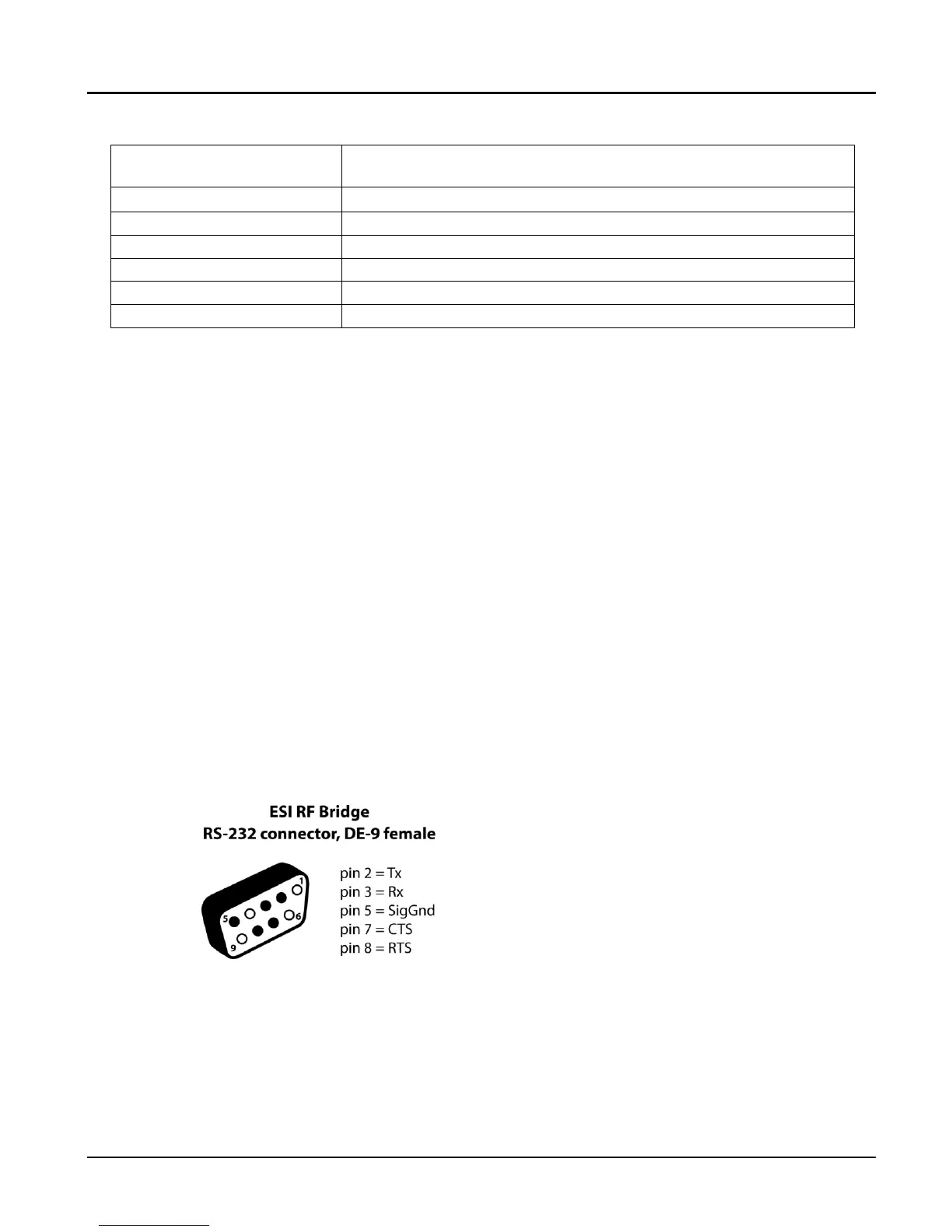
RS-232 Cable and Pinout
Standard DB-9 style to DB-9 style RS-232 serial cables are used to connect a PC/laptop or automation
system to the ESI RF Bridge.
NOTE: the CTS and RTS wires can be omitted when using Xon/Xoff flow control.
1. Hook it up. (also, see the Specifications and Installation Instructions document)
a. Turn on PC and configure terminal program to the correct terminal emulator settings.
b. Connect the RS-232 cable (or USB Serial Adaptor cable) from the PC to the RS-232 port on the ESI RF
Bridge.
c. Connect the “USB to Mini-B” cable from the 5 volt DC external power supply to the ESI RF Bridge.
NOTE: The USB ports are only for power, not data. Plug the cable into the power supply provided.
 Loading...