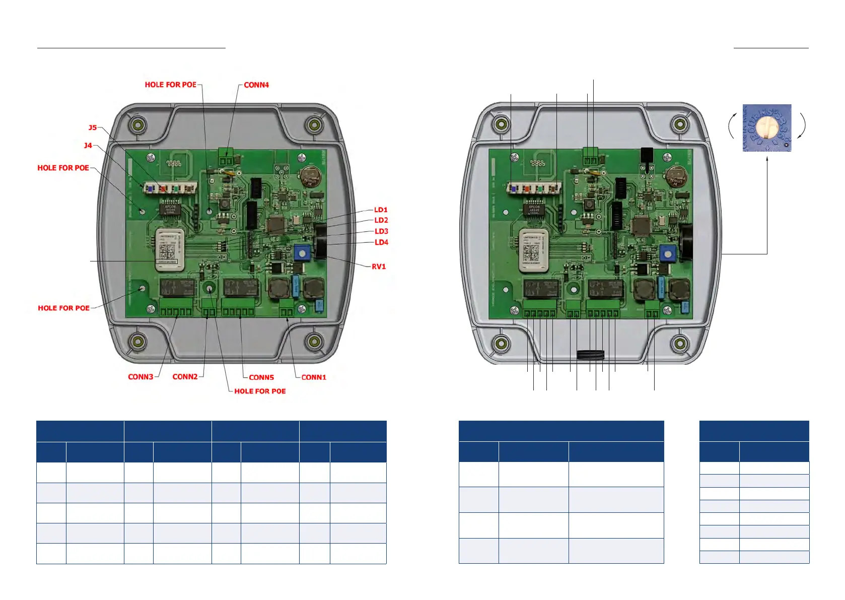
RV1 - Range
Turn clockwise to increase the
detection range or anti-clockwise
to reduce the range
Wiring and Range Adjustment
HARDWARE
ADDRESS
CONN1 : ANT
(2 Way for Antenna)
CONN2 : INPUT
(2 Way for Volt Free Contacts)
CONN3 & 5 : RELAY 1 & 2
(5 Way)
CONN4 : POWER
(2 Way for Power)
Pin No. Description Pin No. Description Pin No. Description Pin No. Description
1 Antenna - 1 0V 1 0V 1 OV IN
2 Antenna + 2 Input + 2 N/O 2 + 24V IN
3 N/C
4 Common
5
+ 24V OUT
(100mA max)
PCB LED INIDICATORS
ID Description Function
LD1 Ethernet Link
LED is ON when Ethernet port has
a valid link
LD2 Ethernet Speed
LED is ON when Ethernet is in
100Mbps mode
LD3 Ethernet Activity
LED blinks when there is activity
on the Ethernet port
LD4 Ethernet Duplex
LED is ON when Ethernet is in half
duplex mode
J4 ETHERNET (8 Way)
Pin No. Description
1 BLUE/WHITE
2 BLUE
3 ORANGE/WHITE
4 ORANGE
5 GREEN/WHITE
6 GREEN
7 BROWN/WHITE
8 BROWN
1
2
3
5
4
1
2
1
2
3
5
4
1
2
1
2
1
8