Do you have a question about the Eurosystems M210 and is the answer not in the manual?
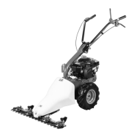
The tag plate with machine data and Serial N° is on the right side of the scythe mower under the engine.
This motor mower is designed and built to mow grass on fodder cropped land. It must only be used with original equipment and spares.
Attention: Before assembly and putting into operation the machine, please read the operating instruction carefully.
A forklift truck should be used to move the machine. Forks should be opened as far as possible and inserted into the pallet.
The scythe – mower is delivered disassembled and placed in a packing case.
The handlebar support tube (2) has to be screwed up to the motor mower frame (4) using the tightening handle (8).
Put the lever (1) on the engine, bring the throttle cable handle (2) to the handlebar, and insert the cable (3) into the hole (4).
The driving cable (1) is already linked to the belt stretcher lever of the frame to the lever (2). Tighten lever (2) with screw (3).
Connect the cable to the black level under the frame, pass it through the nib place, steel ring, nib hole, and red lever.
Assemble the cutting blade device, grease the bar pin, assemble the belt on the pulley and cutting bar, and attach the grass cover.
Fill the engine oil, set throttle to start, switch engine on, adjust revolutions, lower red lever (3) and pull hand driving lever (2).
Adjust belt tension by acting on adjusters (2) to make the bar scythe when the red lever (4) crosses half its way. Unhook safety lever (4).
Ensure wheels turn when driving lever is half-pulled; load spring should extend 6-8 mm when fully pulled. Adjust via nut (1).
Loosen nut (1), position plastic strip (2) to needed height for uneven ground, and tighten nut on both sides.
Regulate knife-guide with screws (1) and locknut after substitution or use. Verify blade movement by turning pulley (2).
Adjust handlebar side and height on 3 positions by turning lever (8) anticlockwise to detach clamping and clockwise to fix.
Ensure nuts/screws are tight. Let machine cool before garaging. Drain fuel tank outdoors. Keep engine area free from debris.
Lubricate gearbox with SAE 80. Verify oil level by unscrewing the cap. Change/check oil every 60 working hours.
Clean and grease the scything bar and all parts mechanisms after every use.
Fill engine oil to the shown level (approx. 0.500 kg). Follow engine producer instructions for oil viscosity.
Clean deeply after use. Protect blade and bar with anticorrosive materials if not used for long periods. Check teeth integrity every 10 hours.
Sharpen cutting sections every 10 hours using an electric sharpening machine (15,000/20,000 rpm) with a 25mm diameter head.
Remove top knife by unscrewing (1) and pulling with pin in hole (2). Replace knife after 2-3 sharpenings or after upper knife changes.
Track: 430 mm. Cutting bar width: 870 mm. Total length: 1500 mm. Height: 1000 mm. Tyres: 13x5.00-6. Mass: 60 kg.
Measured sound power level Lwa = 94.2 dB(A). Sound pressure level Leq = 81.4 dB(A). Handlebar vibration compliance with EN 12733.
Troubleshooting guide for common faults like engine not starting, power loss, irregular cut, or bar/wheels not turning.
| Brand | Eurosystems |
|---|---|
| Model | M210 |
| Category | Farm Equipment |
| Language | English |