Do you have a question about the Eurotherm Drives 631 and is the answer not in the manual?
Essential information before installation.
Information on potential dangers and warnings.
Overview of the 631 Digital Servo Drive and its capabilities.
Procedures for checking the unit upon receipt.
Explains the manual's purpose and intended audience.
Guidance on planning for installation and operation.
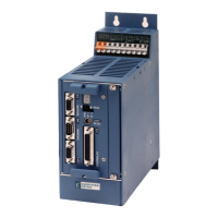
Visual identification of the servo drive's parts.
Overview of the drive's functional capabilities and interfaces.
Explanation of the alphanumeric product code structure.
Guidelines for proper installation to ensure EMC compliance.
Details on physical mounting and dimensions.
Required ventilation space for optimal operation.
Procedures for connecting the drive electrically.
Detailed wiring for motor and main power supply.
Wiring details for the control terminal block.
Instructions for connecting the resolver for position feedback.
Configuring and wiring I/O terminals.
Connecting the drive via the CAN-Bus interface.
Basic principles of drive control and available functions.
Description of the different operating modes available.
Setting up digital and analog I/O for each mode.
Visual representations of input/output signal behavior.
Methods for detecting and preventing motor overload.
How to connect a PC for drive configuration.
Essential checks before applying power to the system.
Step-by-step guide for initial drive configuration using software.
Procedures for optimizing the position control loop performance.
Procedures for optimizing the speed control loop performance.
Steps for tuning the current control loop.
Introduction to the software tool for drive configuration.
Information on the proprietary programming language for motion control.
Using BIAS programs for supervisory monitoring tasks.
Overview of the software's menu structure.
Reference for available commands in the BIAS programming language.
Methods to clear drive trip conditions.
Interpreting the drive's diagnostic display and output states.
Common faults, their explanations, and remedies.
How voltage variations affect drive status.
Storing and accessing past status conditions and errors.
Recommended periodic checks for drive upkeep.
Instructions regarding unit repair and service limitations.
Importance of backing up configuration data.
Procedures for sending the unit for service.
Guidance on environmentally responsible disposal of the unit.
Table mapping ASCII characters to binary and hexadecimal codes.
Conversion table between decimal and hexadecimal values.
Basic environmental and safety information for the unit.
Operating temperature, storage, and other environmental factors.
Details on the electrical isolation principles used.
Guidelines for cabling to meet EMC standards.
Specification of fuses and wire gauges for different models.
Crucial information on proper earthing and safety measures.
Model-specific technical data including EMC and output ratings.
Essential measures for achieving electromagnetic compatibility.
Overview of CE marking requirements and relevant directives.
UL specific requirements for safety and protection.
Formal declaration of compliance with EMC Directive.
Declaration for EMC compliance when used as a component.
Formal declaration of compliance with Low Voltage Directive.
Declaration for compliance with Machinery Directive.
Techniques for controlling synchronous motor types.
Principles and calculations for dynamic braking systems.
Step-by-step calculation for selecting a brake resistor.
How DC Bus ripple affects usable output voltage.
| Enclosure Rating | IP20 |
|---|---|
| Control Modes | Torque, Position |
| Feedback | Resolver |
| Communication | CANopen |
| Protection Features | Overcurrent, Overvoltage, Overtemperature |
| Operating Temperature | 0°C to +40°C |
| Humidity | 5 to 95% non-condensing |
| Drive Type | AC Servo Drive |
| Storage Temperature | -20°C to +60°C (-4 to 140°F) |