Do you have a question about the Eurotron MicroCal 20 Series and is the answer not in the manual?
General safety warnings and conditions of use applicable to intrinsically safe versions of this Multi-Calibrator.
Specific warnings and precautions for using intrinsically safe (IS) models of the Multi-Calibrator.
Details on how to order different models and configurations of the MicroCal 20 series calibrators.
Detailed technical specifications for the MicroCal 20 DPC, P20, and 20T models.
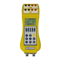
Explanation of the function of each key on the MicroCal 20 calibrator's keyboard.
Description of the MicroCal 20's display elements, symbols, and modes.
Information on how the MicroCal 20 is powered, including battery life and charging.
Guidance on making electrical connections for thermocouples, RTDs, and other inputs/outputs.
Instructions for safely unpacking the MicroCal 20 calibrator and checking for shipping damage.
Procedure for charging the calibrator's battery before first use.
How to switch the instrument on and the initial startup sequence.
Explanation of built-in over-voltage, over-current, and thermal fuse protections.
Covers Data Hold, Zeroing Measure, Storing configurations, and Calculator function.
Detailed procedures for measuring Temperature, Current, Voltage, Resistance, and Frequency/Pulse.
Generating signals for Temperature, Frequency/Pulse, and using Transmitter Simulator.
Using X-Scaling, Graph, Cycle & Ramp, Switch Test, and Leak Test for advanced operations.
Configuring alarms and instrument power-on settings for operational control.
Description of the standard RS232 serial port for communicating with a PC.
How to change the baud rate for the instrument's serial communication.
Step-by-step instructions for installing the driver for the RS232/USB adaptor.
Software for setting up special sensor linearization for the calibrator.
Software for downloading logged data from the calibrator to a PC.
Software for performing and managing test and calibration procedures.
Software for interfacing MicroCal with a PC, running LogMan and LinMan.
Transferring calibration procedures from CalpMan 2007 to the calibrator.
Details on the functions and properties available in the DLL driver for Windows.
Key performance features of the DLL driver, such as serial port management and language compatibility.
Detailed structure of driver functions, including methods, parameters, and results.
Structure of instrument data, including FileName, LastWriteTime, size, Attributes, and Dir.
Parameters accepted by the Setchn method for configuring instrument channels.
Parameters accepted by the Getmeas_output method for reading measurements.
Steps to use the DLL driver in a development environment.
Information about the compiler used for the DLL.
Procedure for testing and calibrating temperature indicators using the calibrator.
Procedure for calibrating TC temperature transmitters to mA output.
Procedure for testing and calibrating 4-20mA pressure transmitters.
Procedure for certifying RTDs using the calibrator as a high accuracy thermometer.
Flow chart illustrating navigation through the calibrator's menu using the MENU key.
Detailed settings for Channel 1, including thermocouple and RTD configurations.
Detailed settings for Channel 2, including various input types and functions.
Settings for the pressure channel, including different pressure units and types.
Table of possible error messages, their problems, and suggested solutions.
How to view the system's status, including external sensors and ambient modules.
Explanation of instrument protections against overcurrent and overvoltage.
Recommendations for storing the instrument when not in use.
List of common spare parts, such as battery packs and chargers.
Details of the Eurotron Instruments warranty policy for its products.
Certification statement regarding the instrument's conformity to standards and specifications.
Performance deviations and specifications for the Intrinsically Safe (IS) models.
Details of ATEX certification and explanation of the ATEX code for IS models.
Special precautions for using the calibrator in hazardous areas.
Warning and procedure for recharging batteries in safe areas only.
Procedure for replacing the battery pack, emphasizing safety in designated areas.
Eurotron Instruments warranty policy for products against defects.
Information regarding WEEE directive and proper disposal of the product.
Statement confirming the instrument's conformity to specifications and standards.
| Brand | Eurotron |
|---|---|
| Model | MicroCal 20 Series |
| Category | Measuring Instruments |
| Language | English |