EVAC reserves the right to make alterations to this specication without prior notice.
© Copyright Evac Oy. All rights reserved.
1
VACUUM TOILET
OPERATION AND MAINTENANCE
Date:
Doc.
09 Nov 2010 002030-2
5775500 CONTROL MECHANISM, EVAC 910, WALL MODELS AND FLOOR MODELS
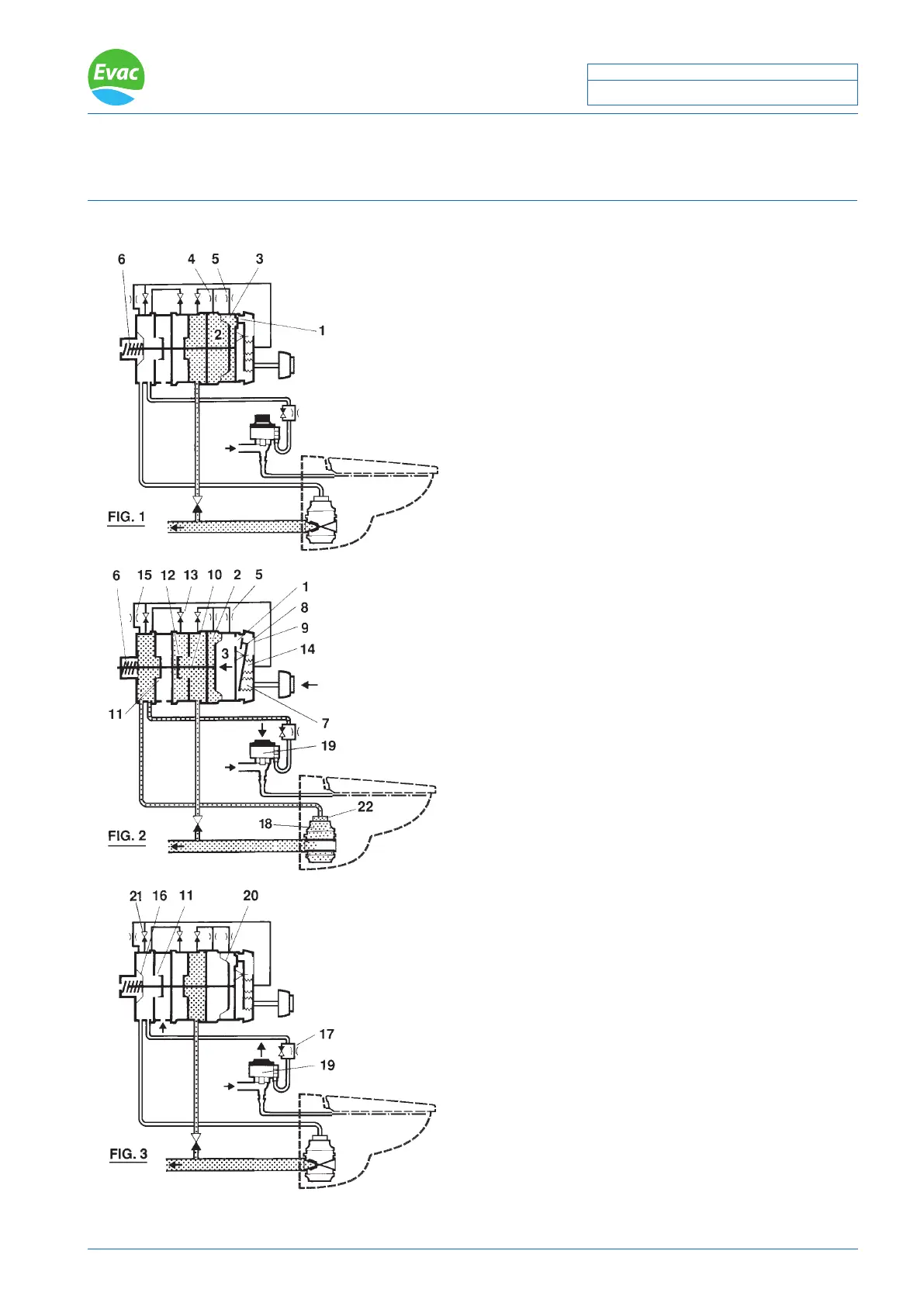
Description of the ushing sequence
In the standby position FIG.1
The control valve (1) is closed. Vacuum in the chambers
(2) and (3) is equalized by the jets (4) and (5). Force of the
spring (6) holds the mechanism in the non-activated position.
In the position immediately after the push button has
been pressed FIG.2
Air pressure applied from the ush button to the chamber
(7) has lifted the lever (8) and opened the control valve
(1). Atmospheric air has entered the chamber (3) through
the lter (9) and the valve (1). The force from the pressure
difference between (2) and (3) has moved the shaft (10) to
the left and the following sequence of events has occured:
The inlet valve (11) has closed. The vacuum valve (12) has
opened. Vacuum is distributed via the check valve (13) to
the discharge valve (18) and the water valve (19) which will
both open. The chamber (14) is also subjected to vacuum
through the check valve (21).
This vacuum will pull the lever (8) and the close valve (11)
and the timer function will start. The chamber (3) will be
evacuated through the jet (5) and the pressure difference
(2-3) equalizes. At the certain level, the counterforce from
the spring (6) will outweigh and the cycle will go in the
opposite direction:
The vacuum valve (12) will close. The air inlet valve (11)
will open and vacuum will enter the relief valve (22), the
athmospheric air enters the water valve, the discharge
valve and the chamber (14). The discharge valve (18) will
close and somewhat later (because of the jet (17)), the
water valve (19) closes when a suitable water level has been
reached at the bottom of the bowl. The relief valve closes.
Returning to the standby position FIG.3
The whole system goes to the standby position ready for
another VT-ush.
! NOTE: The diaphragm (16) has the same effective area as
the air inlet valve (11) to balance the vacuum forces. FIG.3
! NOTE: Check the valve (13) ensures that connected the
valves in the activated position are unaffected by changes
in the vacuum supply level.
! NOTE: If vacuum is too low or absent the function is
delayed. The control valve (1) stays open until the chamber
(14) is subject to vacuum.
 Loading...