Doc. NO.1000624 Page 3
SPECIFICATIONS
Function: Armature mechanism trips on
high vibration and operates snap action
switch(es).
Amplitude Range: See How to Order. "C"
Frequency Range: 0 to 3600 RPM.
Setpoint Adjust: 0 to 100% of range.
External setpoint adjustment.
Reset: Local reset, plus optional remote
reset electrical coil. See How to Order. "D"
Start Delay: Applying reset coil voltage at
start up holds mechanism from tripping for
20-30 seconds, after which the switch is
active. Requires electric reset option.
Temperature Range: -40°C to 70°C
Enclosure: High strength copper-free (4/10
of 1% max) Aluminum alloy.
Environmental Rating: NEMA 4, IP 65 &
CE Mark (NEMA 4X OPTIONAL)
Switch Contact(s) Rating: 15 amps, 125,
or 480 Vac; 1/8 hp, 125 Vac; 1/4 hp, 250
Vac; 1/2 amp, 125 Vdc; 1/4 amp, 250 Vdc.
Hazard Rating: See How to Order. "A"
Weight: 1.8 kg (4.0 lbs.)
A □ Hazard Area Rating
0 = None
1 = UL, cUL Explosion Proof, Class I, Groups C & D, Div 1
Class II, Groups E, F & G, Div 1
2 = UL, cUL Explosion Proof, Class I, Groups B, C & D, Div 1
Class II, Groups E, F & G, Div 1
3 = CENELEC Flameproof, EEx d IIB T6 DEMKO 02 ATEX 0212409
4 = CENELEC Flameproof, EEx d IIB+H2 T6 CE 1180 II 2 GD
5 = Non-Hazardous, Gold Contacts
B
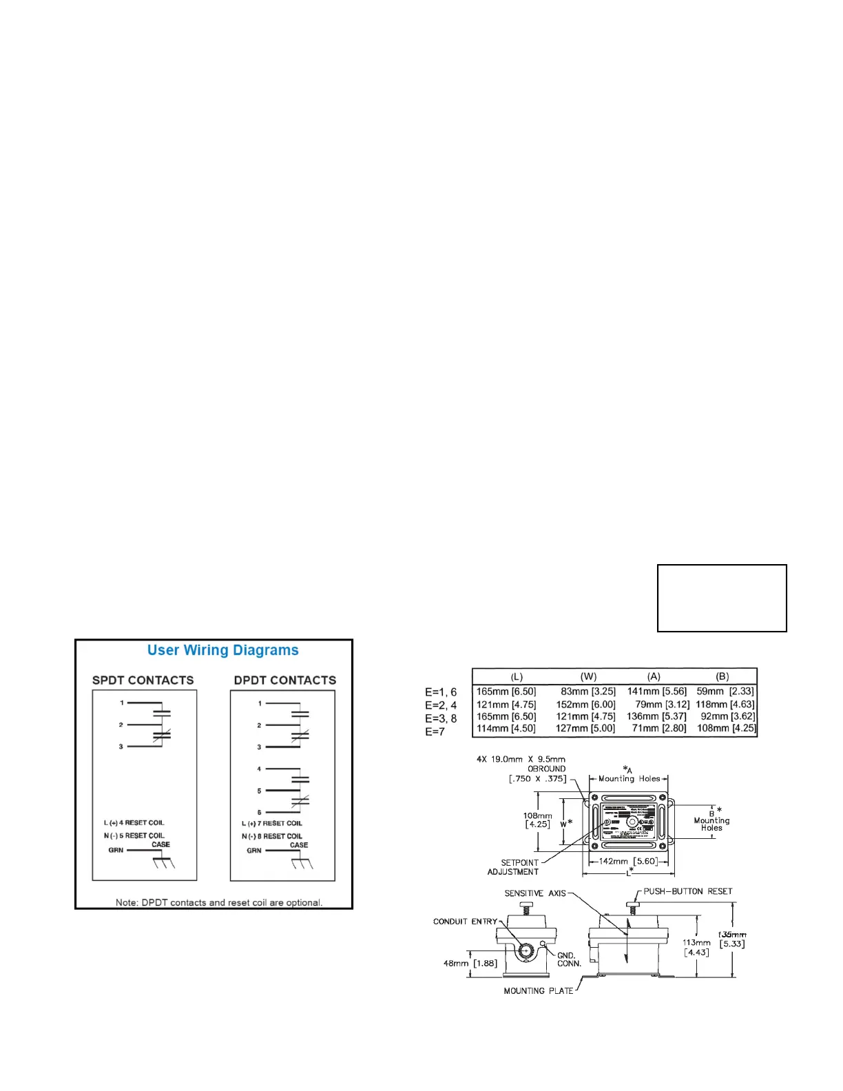
□ Contacts
1= SPDT 2= DPDT
3= SPDT Gold Contacts, 1A 4= DPDT Gold Contacts, 1A
C
□ Full Scale Range
1= 5 g †2= 2 g 3= 10 g
D
□ Reset Coil & Start Up Delay
0= None 1= 115 VAC 2= 230 VAC 3= 24 VDC 4= 115 VDC
E
□ Wiring Entry/Mounting Plate (retrofit)
1= 3/4” NPT/Metrix 5173 or 5175
2= 3/4” NPT/Metrix 5097; VS-2-EX; 366
3= 3/4” NPT/Metrix 5078; 365
4= M20 x 1.5/Metrix 5097; VS-2-EX; 366
6= M20 X 1.5 / METRIX 5173 or 5175
7= 3/4” NPT / PMC/BETA 440
8= M20 X 1.5 / METRIX 5078; 365
F
□ Environmental Rating
0 (or blank) = NEMA 4, IP 65, CE
1 = NEMA 4X, IP 65, CE
MODEL A B C D E F
017-00464P -□□□-□□□
Example: 017-00464P-221-010
Note: When option A1 or A2 is specified, options E4, E6
and E8 are not allowed.
†When Option C=2, Option D can not equal 3 for opera-
tion in the horizontal axis.
Tested for Compliance
with the applicable EC
Electromagnetic Com-
patibility Requirements
DIMENSIONS IN mm (inches)
Mounting Plate for E=1, 6 Shown
 Loading...