EVCO S.p.A.
c-pro 3 nano CHILL | Application manual ver. 3.0 | Code 144CP3NCE304
page 18 of 96
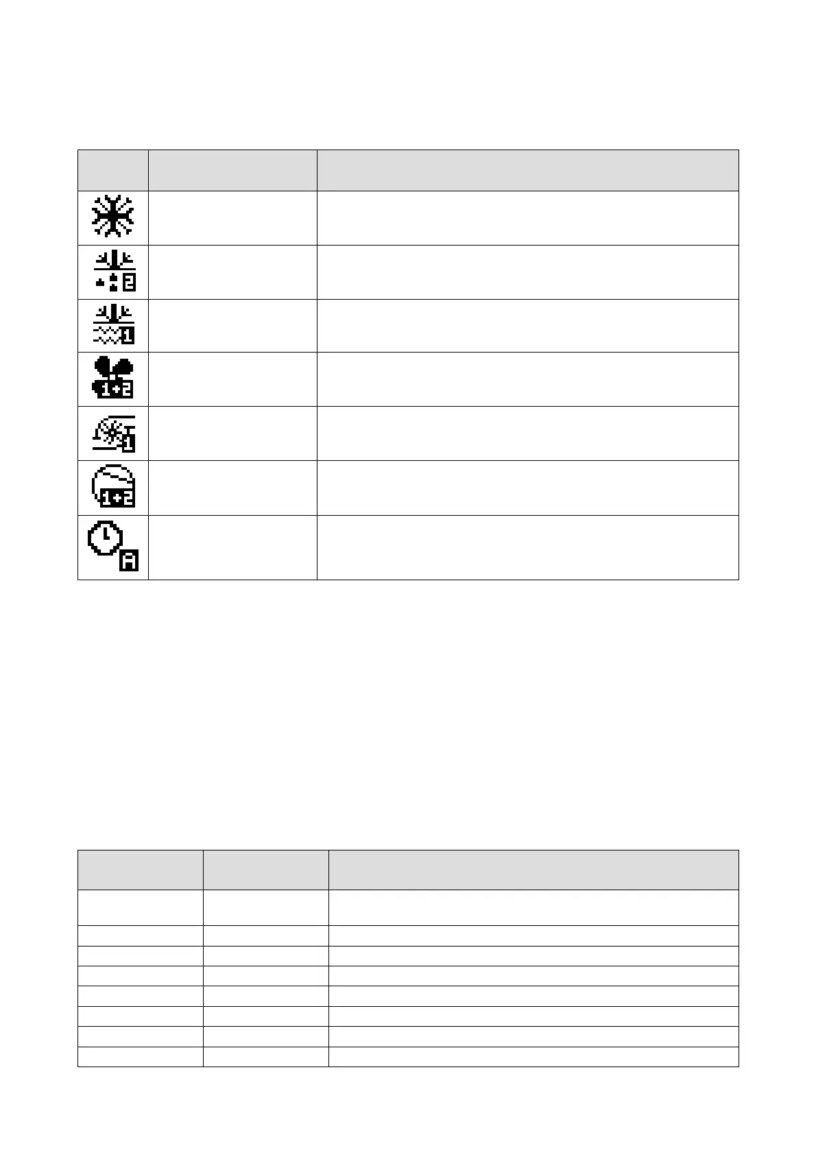
The table below shows the individual icons, their operating state, and what is verified.
From left to right:
Icon
Operating mode
Event shown
Summer/Winter/Alarm Icon
If there is an active alarm, the alarm icon will be shown in place of the operating
mode icon (summer/winter)
Defrost Icon
Means that a defrost is underway in the circuit (1,2).
If it is blinking the dripping phase is underway
Anti-freeze Icon
Means that the antifreeze heaters are active (plant or source)
in the circuit indicated (1,2 1+2)
Fan Icon Means that the circuit fans (1,2, 1+2) are active
Pump Icon Indicates which circulation pump (1,2) is active
Compressor Icon Means that at least one compressor in the circuit (1,2, 1+2) is active
Timer Settings Icon Indicates which timer setting is active (A,B)
From this page, by pressing the RIGHT or LEFT key you can view other information concerning pumps, fans, compressors, defrost,
circuit state, RTC, and all probes configured. If one of the probes is in error, the value field of the corresponding probe shows “----“, or
“----“ if the probe is disabled.
By pressing the ESC key from this page, the user accesses the Alarms page.
On the two-line display, the top line shows the Heat sink exchanger input temperature, while on the bottom display the Heat sink
exchanger output temperature is shown for circuit 1 if there is 1 circuit. If instead there are two circuits, the average of the two
temperatures output from the exchangers is shown (if one of the two probes is in alarm, the value of the one not in alarm is shown).
6.4 StAt Menu
If you choose the Stat item from the general menu you enter the screen of certain main modes of the system (which you can browse
with the Left/Right keys) on the page of reference:
Table with examples of system modes viewable from Page 1
Page of reference Mode shown System mode
Page 1 Unit Indicates the mode the machine is operating in (OFF, ChIL, pdC, dEFr, dRIp,
F-C)
Page 1 ModE Indicates the machine operating mode (ChIL, pdC)
Page 1 tdF1 Accumulation of the wait time for a defrost circuit 1
Page 1 dFr1 Duration time of defrost circuit 1
Page 1 tdF2 Accumulation of the wait time for a defrost circuit 2
Page 1 dFr2 Duration time of defrost circuit 2
Page 1 SEtC Current setpoint summer operation
Page 1 SEtH Current setpoint winter operation

 Loading...


