TIP
After positioning the hinge bar,
press it against the wall to mark the
pilot hole locations.
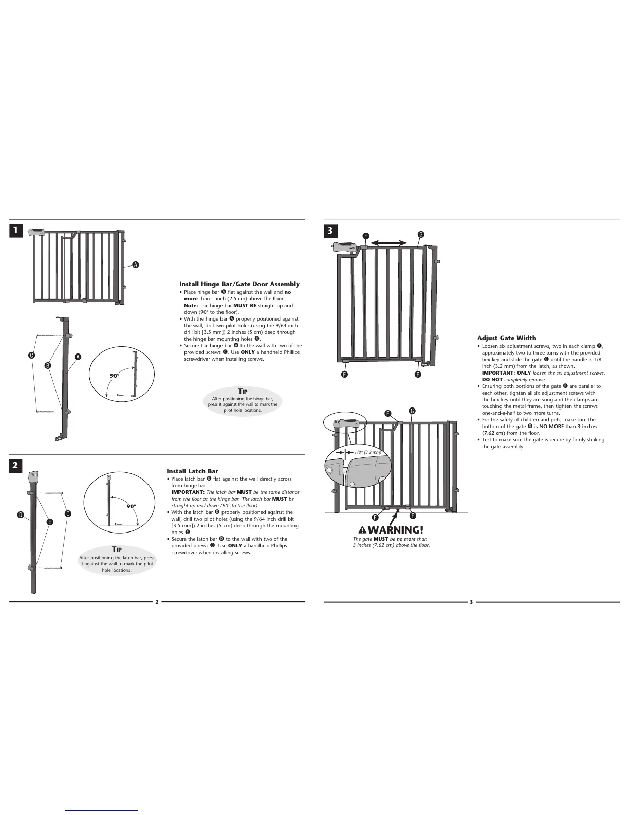
Install Hinge Bar/Gate Door Assembly
• Place hinge bar A flat against the wall and no
more than 1 inch (2.5 cm) above the floor.
Note: The hinge bar MUST BE straight up and
down (90º to the floor).
• With the hinge bar A properly positioned against
the wall, drill two pilot holes (using the 9/64 inch
drill bit [3.5 mm]) 2 inches (5 cm) deep through
the hinge bar mounting holes B.
• Secure the hinge bar A to the wall with two of the
provided screws C. Use ONLY a handheld Phillips
screwdriver when installing screws.
2
3
G
C
B
A
Install Latch Bar
• Place latch bar D flat against the wall directly across
from hinge bar.
IMPORTANT: The latch bar MUST be the same distance
from the floor as the hinge bar. The latch bar MUST be
straight up and down (90º to the floor).
• With the latch bar D properly positioned against the
wall, drill two pilot holes (using the 9/64 inch drill bit
[3.5 mm]) 2 inches (5 cm) deep through the mounting
holes E.
• Secure the latch bar D to the wall with two of the
provided screws C. Use ONLY a handheld Phillips
screwdriver when installing screws.
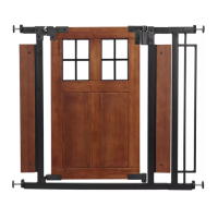
Adjust Gate Width
• Loosen six adjustment screws, two in each clamp F,
approximately two to three turns with the provided
hex key and slide the gate G until the handle is 1/8
inch (3.2 mm) from the latch, as shown.
IMPORTANT: ONLY loosen the six adjustment screws.
DO NOT completely remove.
• Ensuring both portions of the gate G are parallel to
each other, tighten all six adjustment screws with
the hex key until they are snug and the clamps are
touching the metal frame, then tighten the screws
one-and-a-half to two more turns.
• For the safety of children and pets, make sure the
bottom of the gate G is NO MORE than 3 inches
(7.62 cm) from the floor.
• Test to make sure the gate is secure by firmly shaking
the gate assembly.
1
2
E
C
TIP
After positioning the latch bar, press
it against the wall to mark the pilot
hole locations.
D
1/8” (3.2 mm)
The gate MUST be no more than
3 inches (7.62 cm) above the floor.
WARNING!
3
F
F
F
G
F
F
F
A