227
POWERHEAD
POWERHEAD INSTALLATION
11
IMPORTANT: Retighten powerhead mounting
screws after outboard has been run at full operat-
ing temperature and allowed to cool.
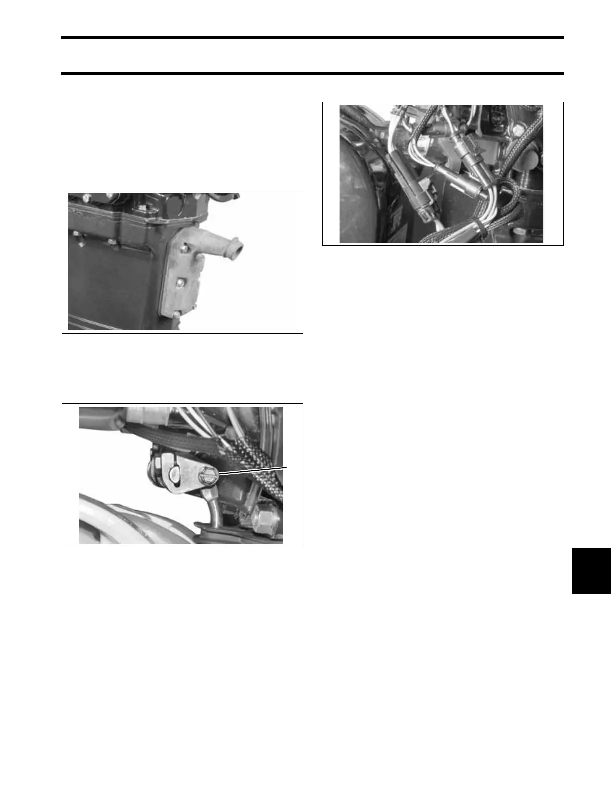
Apply Gasket Sealing Compound to exhaust relief
muffler gasket and retaining screws. Install muffler
and tighten screws to a torque of 60 to 84 in. lbs.
(7 to 9.5 N·m).
Place the shift rod in the shift rod lever. Install the
retaining pin and washer. Tighten pin to a torque
of 60 to 84 in. lbs. (7 to 9.5 N·m).
Check shift linkage adjustment. Refer to Shift
Linkage Adjustment on p. 228.
IMPORTANT: Make sure the gearcase shifts
solidly into both forward and reverse and that pro-
peller shaft spins freely in neutral.
Connect the power trim connectors.
Install the lower engine covers. Refer to LOWER
COVER SERVICE on p. 82.
IMPORTANT: Perform the following procedures
before returning outboard to service:
• Index all spark plugs. Refer to Spark Plug
Indexing on p. 76.
• Adjust timing pointer and check engine timing.
Refer to TIMING ADJUSTMENTS on p. 142.
• Use Evinrude Diagnostics software to start pow-
erhead break-in oiling. Refer to Powerhead
Break-In on p. 98.
• Prime oiling system. Refer to Oiling System Oil
Supply Priming on p. 54.
• Run outboard and check for water, fuel, or oil
leaks.
• Make sure engine reaches correct operating
temperature and does not overheat.
002163
1. Shift rod screw 002013
1
002152
 Loading...