247
MIDSECTION
STERN BRACKET
12
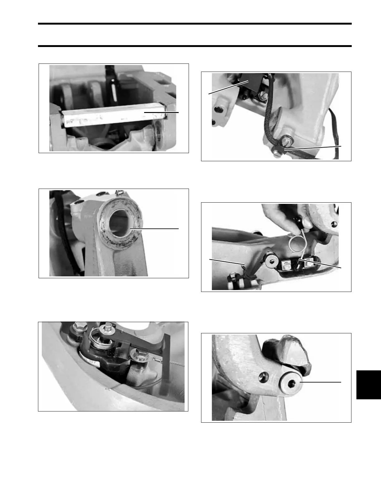
Remove the anode.
Remove the swivel bracket. Inspect and, if neces-
sary, replace the tilt tube bushings.
Remove the trim sender unit from the port stern
bracket and pull its wires through the braided
tube.
Remove the tilt limit switch and retainer from the
swivel bracket.
Disconnect the trail lock spring and remove it from
the swivel bracket. Remove trail arm retainer.
Remove the trail lock arm and bushings from the
swivel bracket.
1. Anode 30762
1. Tilt tube bushing 30761
30760
1
1
1. Tilt limit switch
2. Retainer
30758
1. Trail lock spring
2. Trail arm retainer
30756
1. Trail lock bushing 30755
2
1
1
2
1
 Loading...