269
GEARCASE
GEARCASE DISASSEMBLY
13
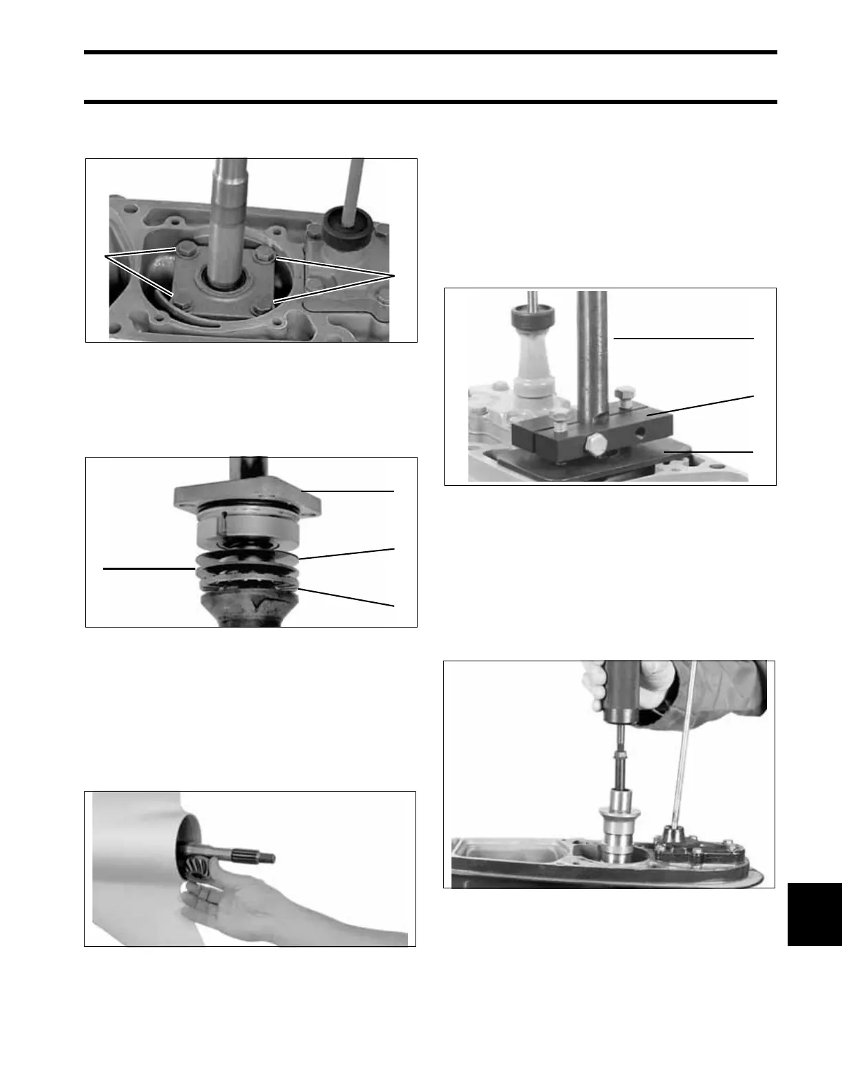
Remove the four driveshaft bearing housing
screws.
Remove pinion nut and driveshaft from the gear-
case. The bearing housing, shims, thrust bearing,
and thrust washer will come out with the drive-
shaft.
If driveshaft cannot be removed, refer to Locked
Driveshaft Removal on p. 269.
Remove the pinion gear and pinion nut from the
gearcase.
Locked Driveshaft Removal
The driveshaft to pinion taper is a locking taper. If
necessary, use Driveshaft Puller, P/N 390706, and
Backing Plate, P/N 325867, to break the lock.
Install the tools as shown by clamping them
around the driveshaft. Alternately tighten the two
vertical screws against the backing plate inserted
between the puller and the gearcase until the
driveshaft pops loose from the pinion.
If upper driveshaft becomes separated from lower
driveshaft, use Lower Driveshaft Puller,
P/N 342681, to remove. Install puller into lower
driveshaft and turn 90° to position hook under pin
in driveshaft. Thread Slide Hammer, P/N 391008,
into puller and remove driveshaft.
1. Driveshaft bearing housing screws COA3153
1. Bearing housing
2. Shims
3. Thrust bearing
4. Thrust washer
COA3558
COA3159
1
1
1
2
3
4
1. Drive shaft
2. Puller
3. Backing plate
41177
46905
1
2
3
 Loading...