29
INSTALLATION AND PREDELIVERY
BOAT RIGGING
2
Typical battery functions
IMPORTANT: Never connect an external battery
isolator to the stator of an Evinrude E-TEC.
Primary
• Used as starting battery under normal operating
conditions.
• Red (+) cable connected to battery selector
switch.
• Primary battery is charged by connection to
main red (+) outboard battery cable.
Dual outboard installations can utilize the oppos-
ing outboard's primary battery as a secondary bat-
tery for emergency starting only.
Secondary
• Used as back-up starting battery under abnor-
mal operating conditions.
• Red (+) cable connected to battery selector
switch.
• Secondary battery is charged independently
from primary battery.
Accessory
• Not used as starting battery.
• Isolated from outboard start function.
• No red (+) cable connected to battery selector
switch.
Battery Switch Requirements
Battery switches must meet the following require-
ments.
• The switch must be approved for marine use.
• The switch should be a “make before break”
design to protect the charging system from a
no-load condition.
• Switch amperage rating should be adequate for
the outboard it will be used on.
• Use one battery switch for each outboard
installed.
• Use the appropriate sized wire and terminals for
all connections.
• Use AWG stranded copper wire.
Battery Switch Location
• Always locate battery switch as close to the bat-
teries as possible.
• Locate switch so that it cannot be accidently
bumped or switched.
• Refer to the battery switch manufacturer’s
installation instructions for specific information
related to the installation of switch.
• Fasten all battery switches to solid surfaces.
• Route wiring as directly as possible.
• Support the battery switch as needed to prevent
abrasion.
• Use appropriate wiring and connectors.
• Seal all connections and terminals with liquid
neoprene or electrical sealer to prevent corro-
sion.
IMPORTANT: Insulate all battery positive (+)
terminals to prevent shorting.
Battery Switch Operation
• Select the primary battery for normal operation.
• Secondary batteries should only be selected for
emergency starting.
• ALL or BOTH switch position is for emergency
starting only.
Provide operator with the documentation sup-
plied by the battery switch manufacturer. Make
sure that the operator is informed of proper
battery switch operation.
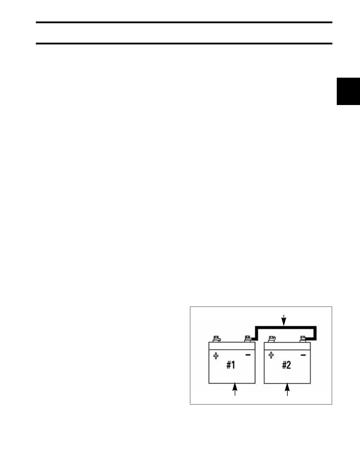
IMPORTANT: The negative (–) terminals of a
multiple 12-volt battery installation must be con-
nected together.
1. Starting battery (primary)
2. Accessory battery (secondary)
3. Cable connecting negative (–) battery terminals
DRC7284
1 2
3
 Loading...