17
evo HE H - Installation & Servicing
INSTALLATION
FLUE OUTLET
1
nm8752
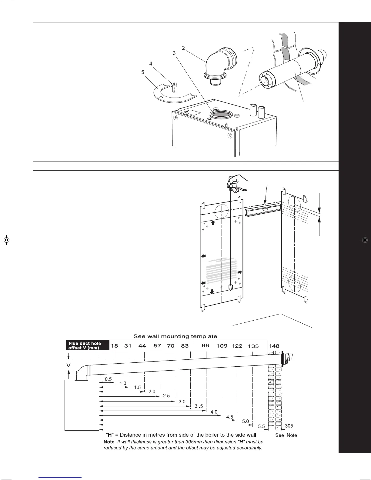
Note.
The template shows the positions of the fixing holes and
the flue hole centres for standard installation and for using
the stand-off kit. Care MUST be taken to ensure the
correct holes are drilled.
1. Separate the templates.
2. Tape template A into the selected position.
3. Ensure squareness by hanging a plumbline as shown. If
fitting a side flue extend the flue centre line onto the side
wall. Tape template B into the selected position.
4. Mark onto the wall the following:
a The 2 wall mounting plate screw positions (choose
one from each group) and the jacking screw position.
If using the stand-off kit mark on 4 screw positions
(choosing one from each group).
b. The position of the flue duct hole (see diagram below,
and template).
Note. Mark the centre of the hole as well as the
circumference
5. Remove the template from the wall.
16
WALL MOUNTING TEMPLATE
15
FLUE ASSEMBLY - Exploded View
LEGEND
1. Duct assembly.
2. Flue turret.
3. Turret gasket.
4. M5 x 10 pozi screw.
5. Turret clamp.
An optional flue duct extension kit is required for
wall thicknesses greater than :
Side 395mm
Rear 435mm
Ecl 2360
V
A
B
Extended centre line
Rear flue arrangement shown
nm8731
203323-2.pmd 21/09/2007, 11:2617
 Loading...