141
www.evolutionbuild.com
®
SV
SK
RU
PT
PL
NO
NL
IT
GB
FR
FI
ES
EL
DE
DA
CZ
ASSEMBLY
1. Connecting the PW3200 Pressure Washer to the
Evolution Evo-System Engine
Note: Your Evolution Pressure Washer is designed to be
connected to and powered by the Evo-System Engine. Do
not try to connect this machine to any other power source.
Your Evo-System Engine has a unique coupling that enables
a variety of Evolution accessories to be connected to and be
driven by this machine. This coupling is engineered to very
fine tolerances and must be kept clean and free from dirt,
debris etc. A cover for coupling protection is provided with
each accessory and should be used whenever the accessory
is ‘remote’ from the engine.If you experience difficulty in
accessory connection, it could be because the accessory
location pins, or the annuli of either the accessory or the
engine are contaminated or damaged.
Preparing the engine for accessory connection:
Note: The Evo-System Engine has a micro switch
incorporated within the coupling design that senses
when an accessory has been successfully attached to the
machine. The engine will not start without an accessory
being successfully connected. It cannot be run as a ‘stand
alone’ machine.
•LocktheTransportationWheelsusingthewheelbrake.
• ReleasetheAccessoryMountingFramebyrotatingthe
locking levers to their unlocked (down) position and push-in.
•DeploytheAccessoryMountingFrame.
• Locktheframeintopositionbypullingoutandthen
returning the locking levers to their locked (upright) position.
Pressure Washer connection
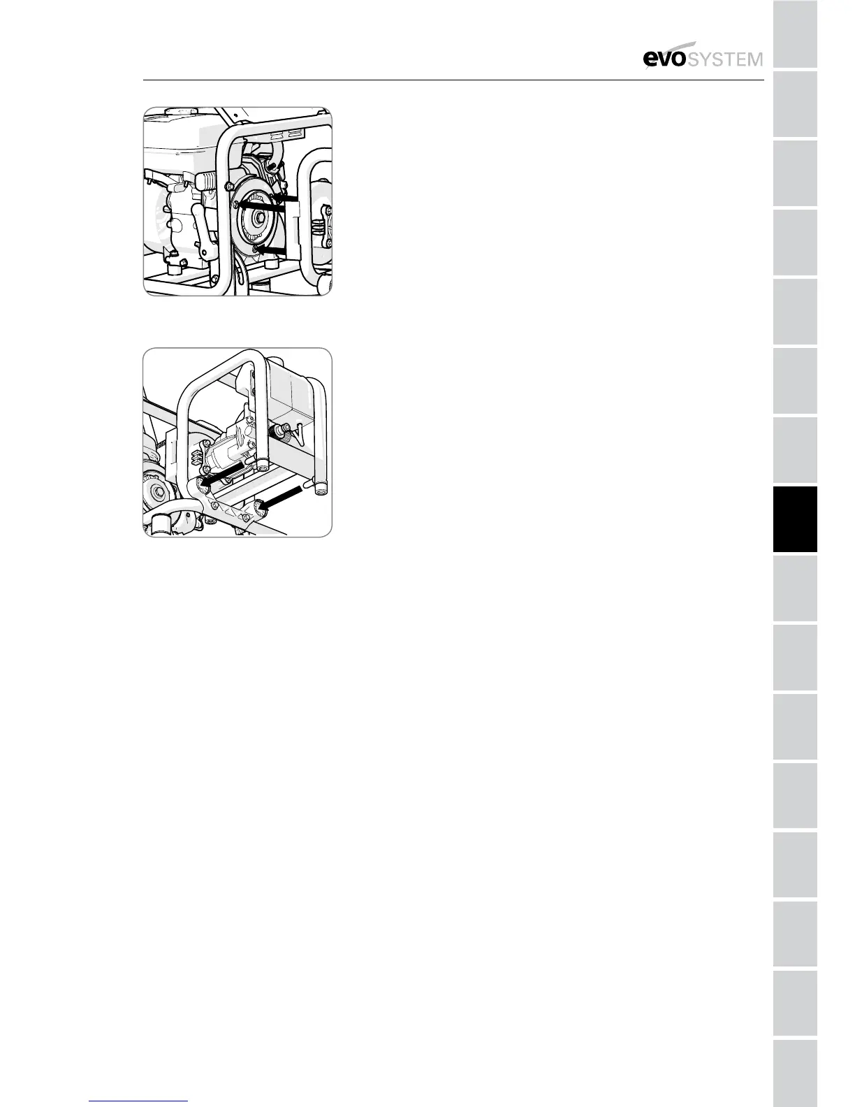
Note: The Pressure Washer is equipped with 3 locating pins
(Fig. 1a) and 2 rear stabilising pins.
The 3 locating pins lock into the ‘Uni-coupling’.
The other 2 stabilising pins slide into the sockets in the
Accessory Mounting Frame. (Fig.1b)
• Holdtheaccessorybyitsexternalframeandofferitup
to the engine. Visually align the 3 locating pins and 2 rear
stabilising pins. Enlist competent help if necessary.
• Holdingontoaconvenientpartoftheexternalengine
frame can aid the operator achieving and maintaining
alignment when connecting an accessory.
• Gentlypushtheaccessoryintotheengine.Keepthe3
locating pins and the 2 stabilising pins aligned with their
respective docking positions. The internal coupling between
the engine and the accessory will be made automatically.
No component alignment or adjustments are necessary.
Fig 1a
(showing 3 locating pins)
Fig 1b
(showing 2 rear stabiliser pins)
 Loading...