Do you have a question about the Evoqua WALLACE & TIERNAN JETPAK and is the answer not in the manual?
Information on assembly, operating, and maintenance personnel needs for the JETPAK system.
Defines the intended audience for the instruction manual, including operators and technicians.
Explains the meaning of pictograms and notes used in the instruction manual for warnings and assistance.
Specifies the approved applications for the JETPAK system and prohibits other uses.
Covers general safety rules, personnel qualifications, electrical safety, and waste disposal.
Details specific safety warnings regarding caustic substances and chemical handling.
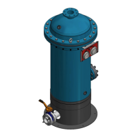
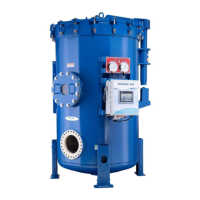
Describes the system components and provides a diagram with numbered parts.
Presents specifications like dimensions, weight, power, and capacity tables for the JETPAK system.
Outlines the physical and chemical properties required for activated carbon used in the system.
Provides guidelines for safe handling, transport, and storage of the system to prevent damage.
Details the steps for unpacking the system and preparing the installation site.
Explains the procedure for installing the stirrer shaft onto the motor.
Covers the electrical connection requirements and safety precautions for mains power.
Describes the terminals for external release contacts used to stop dosage operations.
Explains the non-contact ultrasonic level sensor and its programmed limit levels.
Details how to connect the system to the process water supply, including pressure requirements.
Instructs on connecting the tank overflow and drainage lines for proper disposal.
Provides guidelines for installing dosage lines to ensure correct flow velocity and prevent sedimentation.
Specifies the correct selection criteria and installation for the injection point.
Details the step-by-step procedure for switching on and starting the JETPAK system.
Lists parameters that need modification or can be adjusted, with factory settings.
Explains the use of setup menus for configuring AutoSTART, network interfaces, and maintenance intervals.
Guides through setting up ETHERNET internet configuration and resetting to factory settings.
Describes how to activate/deactivate system components like stirrer, valves, and pumps for testing.
Details how to change the display language of the JETPAK system's interface.
Provides a table of displayable settings, factory defaults, and options for commissioning and modification.
Explains how to choose and configure the communication interface like PROFINET, PROFIBUS, or MODBUS TCP.
Provides technical data and information for connecting the JETPAK system to a PROFINET network.
Details the wiring procedures for installing an Ethernet switch for PROFINET communication.
Explains how to configure the PROFINET IO-Controller using device master data for data transfer.
Provides information on connecting the JETPAK system to a PROFIBUS DP network as a slave.
Lists technical specifications for the PROFIBUS DP slave connection, including hardware and part numbers.
Outlines the wiring instructions for connecting the PROFIBUS DP communication module.
Explains how to configure the PROFIBUS DP-Master using the device master data for data transfer.
Provides information on connecting the JETPAK system to a MODBUS TCP network.
Lists technical specifications for the MODBUS TCP client connection, including hardware and part numbers.
Details the wiring procedures for installing an Ethernet switch for MODBUS communication.
Explains MODBUS functions and data exchange configuration for the MODBUS client.
Guides on how to change the IP address of the CPU for PROFINET and MODBUS communication.
Describes how to connect the JETPAK system to a Process Monitoring System via RS485.
Lists technical specifications for the RS485 connection to the Process Monitoring System.
Details the installation of the RS485 communication board and setting the RS485 address.
Explains the data types, sizes, and value ranges used during process data transfer.
Provides a list of MODBUS registers and their corresponding data descriptions and value ranges.
Provides general information about the touch screen interface and its operation.
Explains the basic display layout and the function of various elements on the HMI control panel.
Explains function keys, message indicator, and procedures for switching the system on and dosing.
Describes how to log in using operator or service passwords to access program menus.
Presents a system diagram illustrating components, their states, and functions.
Shows examples of HMI displays for different system states like suspension tank empty or filled.
Guides through accessing and using operator menus for signal relay, date/time, and dosing point names.
Explains how to access information on operating data, maintenance, and software details.
Details how to access diagnosis screens for checking inputs, outputs, analog values, and system status.
Explains how to view stored messages and fault logs in the message buffer.
Provides a method and example for calculating the required dosage quantity of activated carbon.
Guides on how to refill the suspension tank with activated carbon and the safety precautions involved.
Explains how to set the mode (ON, OFF, AUTO) for individual dosing points and feed rates.
Details how to switch off the dosage function and the associated flushing process.
Covers procedures for short and extended interruptions to system operation.
Details steps for winterizing the system or preparing it for extended periods of non-operation.
Lists operational parameters that can be modified by the operator, such as dosing point names and feed rates.
Explains how to set up a weekly timer program for automatic activation and deactivation of dosing.
Guides on configuring the signal relay to activate functions based on system status or parameters.
Explains how fault and status messages are displayed and interpreted.
Details the meaning of fault messages, their acknowledgement, and remediation steps.
Explains how all stored messages are kept in the message buffer and how to access them.
Describes the system's behavior after a power failure and how to restart dosing.
Provides a schedule of required maintenance tasks, intervals, and necessary parts.
Step-by-step instructions for operator-level maintenance, including sieve replacement.
Instructions for cleaning the tank and the ultrasonic level sensor.
Guides on how to confirm that maintenance tasks have been completed.
Explains the procedure for deleting the message buffer.
Lists recommended spare parts for maintenance at 6-month intervals.
Lists recommended spare parts for maintenance at 1-year intervals.
Lists recommended spare parts for maintenance at 2-year intervals.
Lists recommended spare parts for 1-year maintenance of SIMATIC S7-1200 systems.
Lists recommended spare parts for 2-year maintenance of SIMATIC S7-1200 systems.
Lists spare parts for diaphragm valves and injectors.
Provides instructions for authorized personnel to dismantle the system for disposal.
Outlines requirements for safe and environmentally friendly disposal of equipment.
Explains the proper disposal of electrical and electronic equipment according to regulations.
Provides guidance on the disposal of reusable packaging waste.
Directs users to a website for information on recycling and disposal of equipment.
The main connection plan for the JETPAK system, showing electrical interconnections.
Shows the wiring diagram for a booster pump with a three-phase motor.
Shows the wiring diagram for a booster pump with a single-phase motor.
Specifies the requirements for filters, including grain size, layer thickness, and filtration rate.
Details standard values and procedures for air-water back-washing of filters.
Illustrates the timing sequence of dosage on dosage lines 1 to 3.
Shows functional diagrams detailing the time sequence for single and dual injection point dosing processes.
| Model | JETPAK |
|---|---|
| Manufacturer | Evoqua Water Technologies |
| Brand | WALLACE & TIERNAN |
| Category | Water Filtration Systems |
| Application | Water Treatment |
| Capacity | Varies by model |
| Dimensions | Varies depending on model |
| Weight | Varies depending on model |
| Certifications | NSF/ANSI 61 |
| Control System | Manual or Automatic (PLC) |