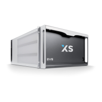
3. Hardware Description
3.1 BOARDS AND SLOT CONFIGURATIONS
The EVS Disk Recorder contains all the EVS developed boards. A single board
configuration is available: 5U Frame
Slot # XS SD, HD or HD/SD
6 Disk Array
5 HCTX
4 CODA (XS Audio Codec)
3 XS COHX (SD, HD or SD/HD) #2
2
XS COHX GLK (SD, HD or SD/HD) #1
Genlock
1 MTPC
3.2 VIDEO AND REFERENCE BOARDS
3.2.1 XS COHX BOARD
The XS COHX board is divided in 3 parts: COHX base (centre front and back),
COD A module (front left), and COD B module (front right).
COD A and COD B modules are the actual CODEC modules, each of them being
able to be configured by software either as an encoder (for a record channel) or
as a decoder (for a play channel). There are 3 hardware versions of COD modules:
SD only, HD only, or HD/SD. They are clearly identified by the sticker at the front
of the board.
There are 2 versions of the COHX base: one with genlock, one without genlock.
The genlock model can easily be identified by the presence of 3 quartz
synthesizer at the back of the board, on the right-hand side, and by the presence
of the GLK and PSU OK LEDs on either side of the DIN connector at the centre
front of the board. Note that a COHX board with genlock must
be installed as
COHX #1 in first position (slot 2) in an XS system. A COHX board with genlock can
never be installed in any other slot, and thus cannot be used instead of COHX #2.
Doing so will result in conflicting electrical signals inside the system.

 Loading...