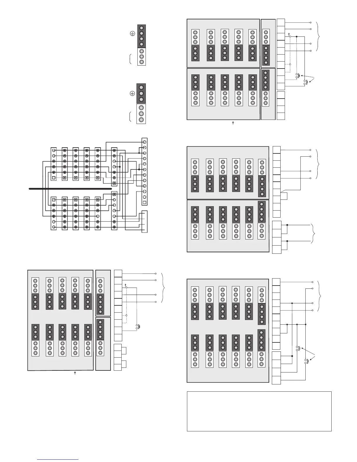
Detector Connection
There are two detector connection positions on each box. The detector is
connected by a flying lead and GST18/7 plug.
Luminaire Connection
There are ten luminaire outlets on each box. Each luminaire is connected by a
flying lead and GST18/6 plug.
Notes:
(i) The dimming control connections are mains rated
(ii) Unit must not be used with multi-phase connections
(iii) Mains-based dimming must not be used in conjunction with
Ex-Or’s range of presence detectors.
Connection Examples
Auxiliary Items
Luminaire Leads:
CPWL633 3m, 3-core, 6-pole GST 18/6 Plug & Ex-Or Latching Shell
CPWL635 5m, 5-core, 6-pole GST 18/6 Plug & Ex-Or Latching Shell
CPWL643 3m, 4-core, 6-pole GST 18/6 Plug & Ex-Or Latching Shell
CPWL645 5m, 4-core, 6-pole GST 18/6 Plug & Ex-Or Latching Shell
CPWL653 3m, 5-core, 6-pole GST 18/6 Plug & Ex-Or Latching Shell
CPWL655 5m, 5-core, 6-pole GST 18/6 Plug & Ex-Or Latching Shell
Emergency Luminaire Leads:
CPWL663 3m, 6-core, 6-pole GST 18/6 Plug & Ex-Or Latching Shell
CPWL665 5m, 6-core, 6-pole GST 18/6 Plug & Ex-Or Latching Shell
Plug & Latching Shell:
CPW7 GST 18/7 Plug & Ex-Or Latching Shell
Detectors:
MS1100PFSWCWL7 Bronze Series Detector with photocell for CDW10U2UL - slimline flush
MS1200PFSWCWL7 Silver Series Detector with photocell for CDW10U2UL - slimline flush
Ensure max
detector load is
not exceeded
Dimming control
See Detector Data
for allowed ballast load
-Switched Live
Neutral
Maintained Live
+
-
Max load 6A
per output
Dimming control -
Detector output
Switched Live
Neutral
Live - Supply to detector
+
-
Push Button input to detector
Single Detector with 10 Luminaires (For load information,
see Note under Technical Data)
A6 A5 A4 A3 A2 A1
Up to 10 luminaires
Detector
B6 B5 B4 B3 B2 Not
used
LK2
LK3
B-
B+
A-
A+
E
ML
E
N
L
E
L
ML
SWB
SWA
PB-B
PB-A
N
From
Supply
Isolator
L
no
connection
Manual
control
Distribution Unit with Mains-Based ‘OneTouch’ Dimming
(for use with compatible Digital Ballasts)
no
connection
no
connection
no
connection
no
connection
A6 A5 A4 A3 A2 A1
Up to 12 luminaires
B6 B5 B4 B3 B2 B1
Remove
Links
LK2 and LK3
Remove
Links
LK2 and LK3
A-
A+
B-
B+
E
ML
E
N
L
E
L
ML
SWB
SWA
PB-B
PB-A
N
From
Supply
Isolator
L
Manual
control
Distribution Unit with Mains-Based ‘OneTouch’ Dimming
(for use with compatible Dimmable Ballasts)
Up to 6 luminaires
B6 B5 B4 B3 B2 B1
A6 A5 A4 A3 A2 A1
Up to 6 luminaires
E
ML
E
N
L
E
L
ML
SWB
SWA
PB-B
PB-A
N
From
Supply
Isolator
L
LK1
LK1
no
connection
no
connection
no
connection
no
connection
no
connection
A-
A+
B-
B+
From
External
Dimming
Control
Two Detectors (For load information, see Note under Technical Data)
LK1 is not required for analogue or switching type of detectors
E
ML
E
N
L
E
L
ML
SWB
SWA
PB-B
PB-A
N
From
Supply
Isolator
L
Detector
Detector
GROUP B
B6 B5 B4 B3 B2 B1
GROUP A
B-
B+
A-
A+
Manual
control
A6 A5 A4 A3 A2 A1
If sockets A1 and B1 are not occupied by presence detector, those sockets may be
used for luminaires, however the plug will need to be 7-pole and wired appropriately.
LK1 is not required for analogue or switching type of detectors
Maintained Live
Live In
Live In
Neutral
Earth
Earth
SWA
SWB
PushButton-A
PushButton-B
Spare
Spare
B-
A-
B+
A+
Group A
Top
Half
Bottom
Half
Group B
Detector A
Detector B
A simple schematic showing connection information (including two spare
terminals) follows:
LK1
LK1
 Loading...