J1
J2
INPUT AC 100V-240V 50/60Hz
SEE INSTRUCTION MANUAL
70C MAX OPERATING TEMPERATURE
29.50
40.40
122.00
46.00
23.50
23.50
80.00
92.00
19.00
19.00 127.00
SLOT F
SLOT E
SLOT D
SLOT C
SLOT B
SLOT A
19.00
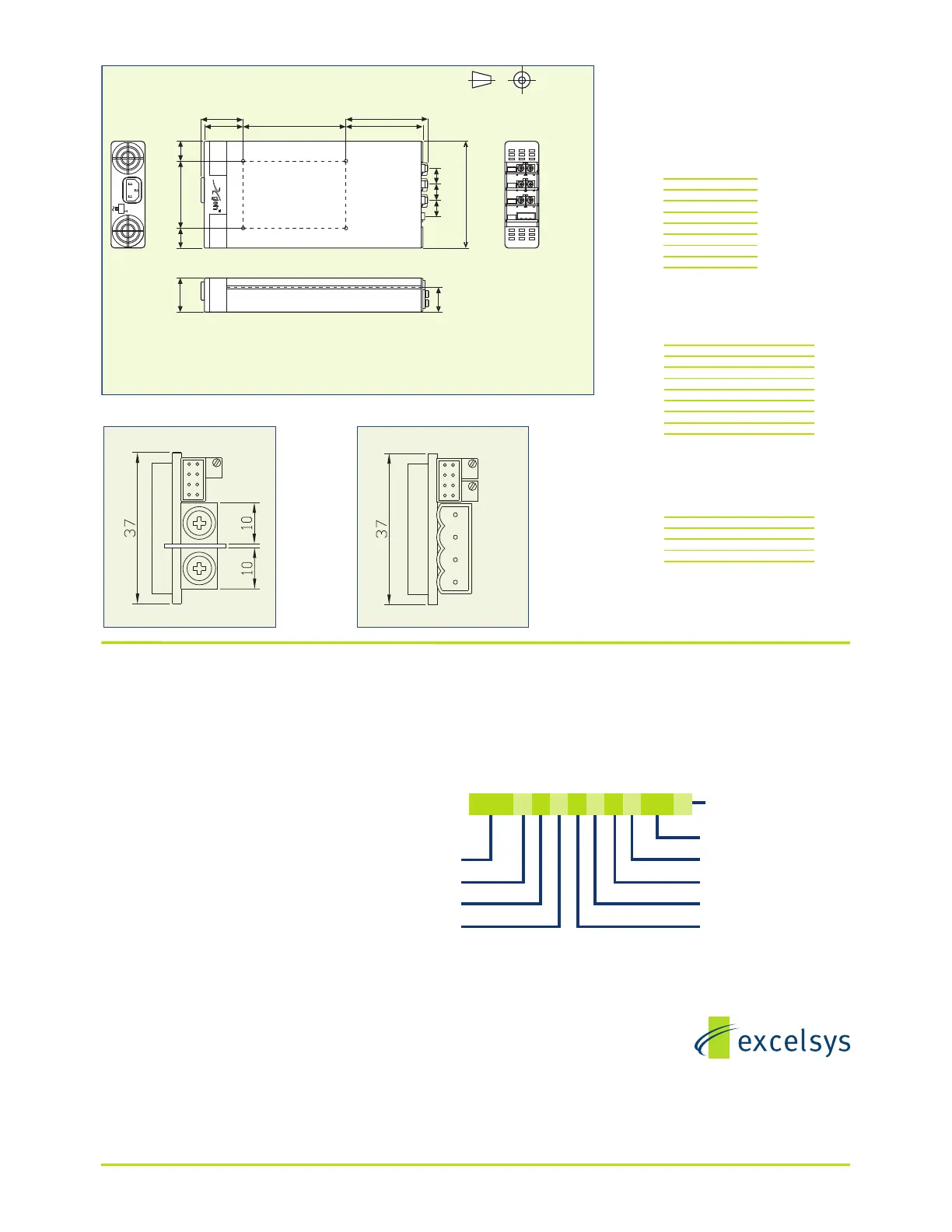
Third angle projection
TOP VIEW
All dimensions in mm.
Mounting Holes
4 M4 threaded holes on Base. Max screw penetration is 6mm from Base.
Fleximount Side Mounting Slots
Use with self-clinching studs type FH-M4-X or FH-832-X (X= stud length) from PEM, or equivalent
Alternatively, use Xgen Side Clamps from Excelsys. Part No. Z165 (drawing 61401)
50.00
97.75
Excelsys Technologies Ltd. reserves the right to alter or improve the specification, internal design or manufacturing process with-
out notice. Please check with your Excelsys represenative or visit www.excelsys.com to ensure that you have the current and com-
plete specification for your product before use. For information and instructions on use, please consult the Xgen Designers’ Manual.
Excelsys Technologies Ltd.
27 Eastgate Drive,
Eastgate Business Park,
Little Island, Co. Cork, Ireland
tel: +353 214354716
fax: +353 214354864
email: sales@excelsys.com
Pin J2 powerPac
1 Common
2 +5V Bias
3
4 AC Fail
5 Fan Fail*
6 Global Enable
7 Temp Alarm*
8 Global Inhibit
J1: Input Mains Connector
IEC320
Note: For use in ambient temperatures >60C, a
hot condition mating connector and cable must be
used.
J2: powerPac Signal Connector
J3: powerMod Signal Connector
powerMod Type B
powerMod Type A
Pin Type A Type B
1 +Sense -PG (V2)
2 -Sense +PG (V2)
3 Vtrim Inhibit (V2)
4 Itrim Common (V2)
5 +Inhibit/Enable -PG (V1)
6 -Inhibit/Enable +PG (V1)
7 +Power Good Inhibit (V1)
8 - Power Good Common (V1)
J4: powerMod Output Connector
Pin Type A Type B
1 -Vout - V2
2 +Vout +V2
3 -V1
4 +V1
Type A : M4 Screw Terminals
Type B : Mating part:
Camden - CTB9200/4A
Note: Cables must be rated 105C minimum (style
UL1015 or equivalent)
Connectors and Pin-Outs
Labeling and Model Numbers
powerMod
powerMod labels contain:
..Minimum, Nominal & Maximum voltage adjustment range.
..Maximum current (Imax)
..Maximum power (Watts)
..Model number
Model numbers are easily identified by the number marked on the top of signal con-
nector J3.
powerPac
powerPac labels contain:
..Input Freq
..Input Voltage
..Fuse rating
..Serial Number
..Maximum combined power rating of inserted powerMods
..Maximum Line current under rated conditions
..Model Number in the format XCD [] [] [] [] [] [] - 01 as an example for a 1200W Xcite
model, with optional Thermal Signals.
When the powerPac has no powerMods inserted, its Model number is simply XCD-01.
When the powerPac has one or more powerMods inserted, its model number may be
easily read to be XCD012340-01 as an example, where powerMods XG1, XG2, XG3,
XG4 are inserted in Slots B,C,D,E respectively with slot covers in the remaining slots A
and F.
Model
Slot A
Slot B
Slot C
Sum of option codes
‘-’ = standard; ‘P’ = preset
Slot F
Slot E
Use ‘0’ for
Slot D
unused slots.
Factory use only
}
XCC 031 3 4 5 P A62
Xgen Series Part Numbering System
Document No. 41002 Rev. 11
Mating parts:
Housing Molex p/n 51110-0850 or -0860
Crimp Terminal Molex p/n 50394
Mating parts:
Housing Molex p/n 51110-0850 or -0860
Crimp Terminal Molex p/n 50394
 Loading...