- 7 -
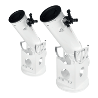
STEP 5 (Fig. 7):
1. Set up the front part (Fig. 1, F) and put it with the drill holes of the
quick fasteners (Fig. 1, M) over the threaded bolts (Fig. 1, L) of the
left side part (Fig. 1, C).
2. Tighten the quick fasteners with a Phillips screwdriver.
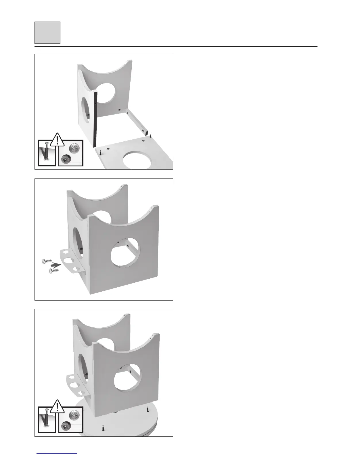
STEP 6 (Fig. 8):
1. Set up the right side part (Fig. 1, D) and put it with the drill holes
of the qick fasteners (Fig. 1, M) over the remaining threaded bolts
(Fig. 1, L) of the bridge (Fig. 1, E) and the front part (Fig. 1, F).
2. Tighten the quick fasteners with a Phillips screwdriver.
3. Use two woodscrews (Fig. 1, N) to attach the accessory tray
(Fig. 1, G) to the front part.
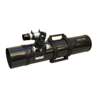
STEP 7 (Fig. 9):
1. Put the complete base construction with the drill holes of the quick
fasteners at the bottom first (Fig. 1, M) over the threaded bolts
(Fig. 1, L) of the prepared bottom plate construction.
2. Tighten the quick fasteners (Fig. 1, M) with a Phillips screwdriver.
Setup
III
Fig. 7
Fig. 8
Fig. 9
max.
4 mm
Fig. A1
max.
4 mm
Fig. A1