Test 3: Voltage Drop Measurements
To determine voltage drop, the CT70 measures line voltage, factors in the load, measures the loaded
voltage, and then calculates the voltage drop. Results for 12A, 15A, and 20A loads are provided. For
nominal efficiency, a voltage drop of 5% is the maximum recommended by the National Electrical
Code (NEC) board. When a voltage drop measurement of less than 5% is made, the meter’s display
backlight turns blue in color. If the voltage drop is higher than 5%, the meter display appears in red.
An efficient branch circuit should have less than 5% voltage drop at the furthest receptacle from the
breaker panel at the termination of the cable run. A steady decrease in the voltage drop should then
be measured for each receptacle tested in sequence towards the breaker panel.
If the voltage drop is higher than 5% and does not noticeably decrease as the testing moves closer
to the first device on the circuit, then the problem lies between the first device and the breaker panel.
Visually check the terminations at the first device, the wiring between the device and the panel, and
the circuit breaker connections.
High resistance points can be identified as hot spots using an infrared (IR) thermometer or by
measuring the voltage across the breaker. If a voltage drop measurement exceeds 5% but noticeably
decreases as the testing moves closer to the panel, then the circuit may have an undersized wire,
too long of a cable run, or excessive current on the circuit. Check the wires to ensure that they are
sized per code and measure the current on the branch circuit. If a voltage drop reading changes
significantly from one receptacle to the next, then the problem could be a high impedance point at or
between two the receptacles. It is usually located at a termination point, such as a bad splice or
loose wire connection, but could also be a faulty receptacle.
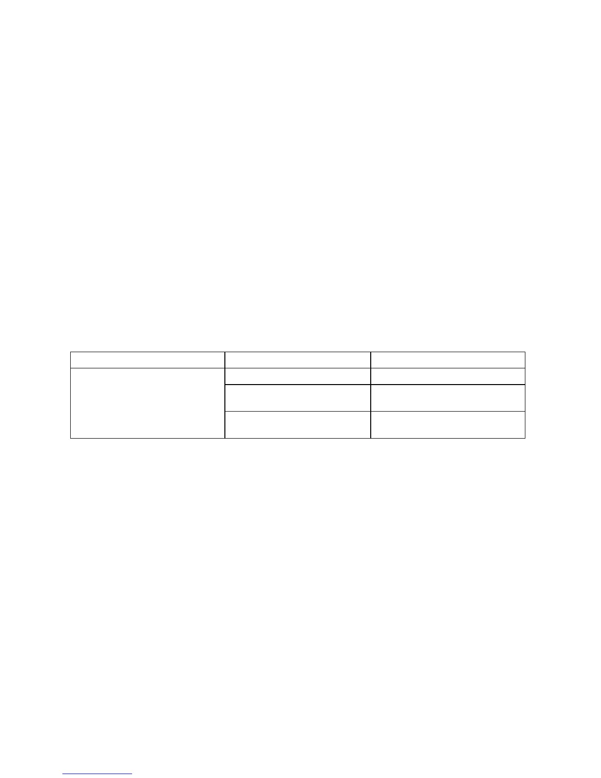
Voltage Drop Measurement Troubleshooting Suggestions
Problems Likely Causes Possible Solutions
Overloaded circuit Redistribute loads
Wrong wire gauge size for
length of cable run
Check code and rewire if
necessary
Voltage drop > 5%
High resistance connection in
the circuit or at the panel
Locate bad connection and rewire
or replace
Test 4: ASCC Measurements
The CT70 calculates the ASCC (Available Short Circuit Current) that a branch circuit can deliver
through a breaker in a dead short circuit condition.
The ASCC is calculated by dividing the line voltage by the circuit’s line impedance. See equation
below:
ASCC = Line Voltage / Hot impedance + Neutral impedance
Use the ► button to simulate a situation where all three conductors (hot, neutral, and ground) are
shorted together. Note that this second test will trip a GFCI.
 Loading...