Installing a Summit Family Switch
Extreme Networks Consolidated ExtremeXOS Hardware Installation Guide
285
Installing a Summit Family Switch
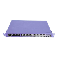
A Summit family switch can be mounted in a standard 19-inch (48.26 cm) rack or placed free-standing
on a tabletop. The installation process includes the following tasks:
● Install the switch in a rack or on a table.
● Ground the switch (DC-powered units only).
● Connect a redundant power supply (if applicable).
● Connect power cables.
If you are installing Summit family switches for use in a SummitStack configuration, read “Building a
SummitStack Configuration” on page 280 before you install the switches.
For information about grounding and connecting DC-powered Summit X450 family switches, see
“Installing and Removing Summit X450a Series DC-Powered Switches” on page 286.
For information about installing and connecting redundant power supplies, see Chapter 5, “Summit
External Power Supplies (EPS).”
Rack-Mounting a Summit Switch
To install the switch in a rack, you will need the following tools and equipment:
● Mounting brackets (provided)
● Eight screws (provided) to secure the mounting brackets to the switch
● Four rack system mounting screws
The screw size will vary based on your organization’s rack system; screws are not provided.
● Screwdriver for securing the switch to your organization’s rack system
The screwdriver size will vary based on the requirements of your organization’s rack system.
To rack-mount a Summit switch:
1 Place the switch upright on a secure, flat surface, with the front facing you.
2 Locate a mounting bracket over the mounting holes on one side of the unit.
3 Insert the screws and fully tighten with a suitable screwdriver, as shown in Figure 199.
Figure 199: Attaching the mounting bracket
4 Repeat steps 2 and 3 for the other side of the switch.
S450_00

 Loading...
