Installing Modules and Establishing Initial Management Access
BlackDiamond 8800 Series Switches Hardware Installation Guide
120
Removing a BlackDiamond 8000 Series Module
BlackDiamond 8800, and 8900 series modules have two styles of ejector/injector levers. Pay careful
attention to the instructions in step 2.
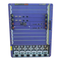
This section describes how to remove modules from a BlackDiamond 8800 series switch. BlackDiamond
modules are hot-swappable. You do not need to power the system off to remove a module.
You need the following tools and equipment to remove a BlackDiamond 8500,8800, or 8900 series
module:
● ESD-preventive wrist strap
● #2 Phillips screwdriver
● Replacement module or blank front panel if you are not replacing the module
To remove a BlackDiamond module:
1 Attach the ESD-preventive wrist strap to your bare wrist. If it is not already connected, connect the
metal end to the ground receptacle at the top left corner of the chassis.
2 Unlock the module in one of the following ways:
● On a module without red lines on the screwheads, turn each captive screw counter-clockwise
(Figure 77). Verify that the yellow band around the captive screw head of each injector/ejector
handle is completely visible (Figure 77). This position ensures that the module is unlocked.
● On a module with red lines on the screwheads, turn each captive screw counter-clockwise
one-quarter turn (90 degrees) (Figure 77). Verify that the red line on each captive screw is in a
horizontal position (Figure 78). This position ensures that the MSM or I/O module is unlocked.
Be sure to turn each captive screw only 90 degrees or one-quarter turn counter-clockwise. Loosening
the captive screws beyond 90 degrees will damage the injector/ejector handles on the module.
Figure 77: Unlocking a Module
 Loading...