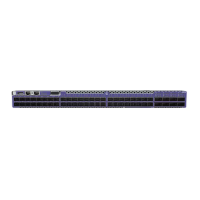
Monitor the Switch
System Status LEDs on page 78
RJ-45 Management Port LEDs on page 79
SFP+/SFP28 Port LEDs for the 7520-48Y-8C on page 80
1G/10G RJ45 Port LEDs for the 7520-48XT-6C on page 81
QSFP28 Port LEDs on page 81
800 W AC Power Supply LEDs on page 82
800 W DC Power Supply LEDs on page 82
The following topics help you monitor the status of the switch as it is running.
System Status LEDs
System status LEDs are located on the front of the switch. The following table describes
the colors and the states for the LEDs.
Table 13: System Status LEDs
LED Color/State Description
Power Off No power; some power rails are
dropping below specication
Green Valid power. All monitored voltages
are nominal.
System Off Boot failed.
Green Operational.
Blinking amber Booting.
Amber Fault.
Fan Status Off No power.
Green Fan is operational.
Amber Fan failure.
78 Extreme 7520 Hardware Installation Guide

 Loading...