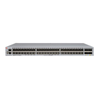
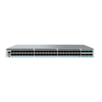
FIGURE 70 Examples of airow symbols
The green E symbol indicates an exhaust FRU. This unit pulls air in from the port side of the device and exhausts it out the non-port side.
This is called front-to-back airow or exhaust airow. This symbol should appear on FRUs with part numbers ending with -F.
The orange I symbol indicates an intake FRU. This unit pulls air in from the non-port side of the device and exhausts it out the port side.
This is called back-to-front airow or intake airow. This symbol should appear on FRUs with part numbers ending with -R.
FRU replacement in a VDX 6740
Field replaceable units (FRUs) in the ExtremeSwitching VDX 6740, consist of combined power supply and fan assemblies. This section
includes procedures to remove and replace these assemblies, time and items required for replacement, and determining if replacement is
needed, and procedures to remove and replace the combined power supply and fan assemblies.
ExtremeSwitching Network OS
identies the power supply and fan assemblies from left to right as power supply and fan assembly #2
and power supply and fan assembly #1 when viewed from the non-port side of the device. For locations of these assemblies, captive
screws, LEDs, labels, and other components, refer to the non-port side view of the VDX 6740 in Hardware components on page 18.
NOTE
Maintain all power supply and fan assemblies in operational condition to provide redundancy.
CAUTION
Because the cooling system relies on pressurized air, do not leave any of the power supply and fan assembly slots empty
longer than two minutes while the switch is operating. If a power supply orand fan assembly fails, leave it in the switch until
it can be replaced.
FRU replacement in a VDX 6740
ExtremeSwitching VDX 6740 Hardware Installation Guide
110 9036108-00

 Loading...


