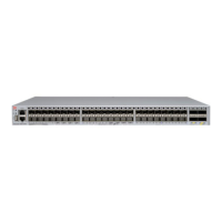
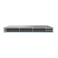
6. Install the new FRU in the chassis:
a) Orient the new power supply and fan assembly with the captive screw on the right as shown in the following illustration.
b) Gently push the power supply and fan assembly into the chassis until it is rmly seated.
CAUTION
Do not force the installation. If the power supply and fan assembly does not slide in easily, ensure that it is
correctly oriented before continuing.
c) Using the Phillips screwdriver, secure the power supply and fan assembly to the chassis by tightening the captive screw.
FIGURE 71 Orientation of the AC or DC power supply and fan assembly in the VDX 6740
1. VDX 6740 chassis
2. AC or DC power supply and fan assembly
3. Label with part number
4. Captive screw
7. Verify that the power supply and fan assembly status LED is steady green to indicate normal operation.
Refer toLED activity interpretation on page 99 for more LED information.
Display the power supply and fan assembly status using the following Network OS commands:
• – show system
– show environment fan
– show environment power
FRU replacement in the VDX 6740T
Field replaceable units (FRUs) in the VDX 6740T include separate power supply and fan assemblies. This section provides details on
removing and replacing these FRUs, time and items required for replacement, and determining if replacement is needed.
Network OS
identies the power supply assemblies from left to right as power supply #2 and power supply and power supply #1 when
viewed from the non-port side of the device. For locations of these assemblies, captive screws, LEDs, labels, and other components,
refer to the non-port side view of the VDX 6740T in Hardware components on page 18.
FRU replacement in the VDX 6740T
ExtremeSwitching VDX 6740 Hardware Installation Guide
112 9036108-00

 Loading...


