MLC 60 Series • Setup Guide (Continued)
2. Change the faceplate, buttons, and volume control knob as needed.
a. (MLC 64 RS VC D only) If changing the faceplate on the MLC 64 volume
control module, rst remove the volume knob (see Removing the Volume
Control Knob on page 4).
b. Remove the faceplate from the MLC module (see Removing the Faceplate on
page 4).
c. If desired, replace the buttons in the faceplate (see Replacing the Buttons on
page 4).
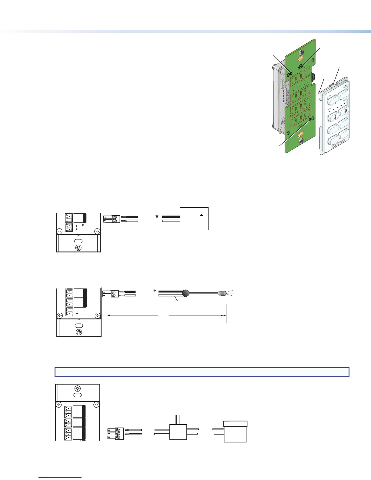
d. Reattach the faceplate as follows (see the illustration at right): Making sure that
both the MLC and the board are upright, line up the tabs at the top and bottom
of the faceplate with the slots on the board, and press the faceplate into the
board until the tabs snap into place. The pegs in the upper-left and lower-right
corners of the faceplate should be seated in the two diagonal holes on the MLC
board.
e. (MLC 64 RS VC D only) If changing the volume control knob, press the new
knob onto the spindle of the volume control module, making sure that the
spindle is turned all the way to the left and that the dot on the knob is aligned
with the bottom edge of the volume icon on the faceplate. Tighten the hex
screw by rotating it one-half turn clockwise.
3. Connect the cables to the rear panel ports. Attach the cables and IR emitters to the rear panel of the MLC and to the
display device or switcher as required.
• Port A Com (RS models only) — Connect a display device or switcher to this serial port to be controlled via RS-232.
MLC RS D Rear Panel
COM
PORT A
Tx G
IR/S
PORT BR
SG
D IN
IN G
RELAYS
12C
REMOTE
Tx Rx G
PWR
12V
0.4 A MAX
Ground ( )
Transmit (Tx)
Ground ( )
Receive (Rx)
Display Device
• Port B IR/S (RS models) or Port A IR (IR models) — Connect a display device, switcher, or up to two IR emitters to
this port. On RS models, you can congure Port B IR/S for either serial or IR communication, using the MLC 60 Series
conguration program. On IR-only models, Port A IR supports only an IR connection.
COM
PORT A
Tx G
IR/S
PORT BR
SG
RELA
12
PWR
12V
0.4 A MAX
Unidirectional IR Output
via White Striped Wire
100'
(30.5 m)
Ground ( )
IR Signal
IR Emitter
• Relays port (RS models only) — The Relays port provides connections for two relays. Connect one or two devices
(such as a low-voltage controller and a motorized screen, shown in the example below) to this port. The relay ports are
normally open and rated for 24 VDC, 1 A (see the example below).
NOTE: If you are using both relay ports, connect the ground wires of both devices to common pin 3.
Ground
Ground
Signal 110/220 V
Low Voltage
Screen Control
Motorized
Screen
Power
Supply
1
2
3
Pin:
A
G
IR/S
PORT BRS-232
SG
D IN
IN G
RELAYS
12C
REMOTE
Tx Rx G
MLC RS D Rear Panel
VOLUME
DISPLAY
OFF
ON
MUTE
LAPTOP
VIDEO
PC
Insert peg
on faceplate
into hole.
Peg
Insert peg
on faceplate
into hole.
Insert tab on
faceplate
into slot.
Ta b
2
 Loading...

