Page 16 of 77
3. RAMPS
3.1. CONNECT RAMP SECTIONS
3.1.1. Place the walking surface side of the ramp sections face down, onto cardboard or lawn so
that the ramp is not scratched, dented, or damaged.
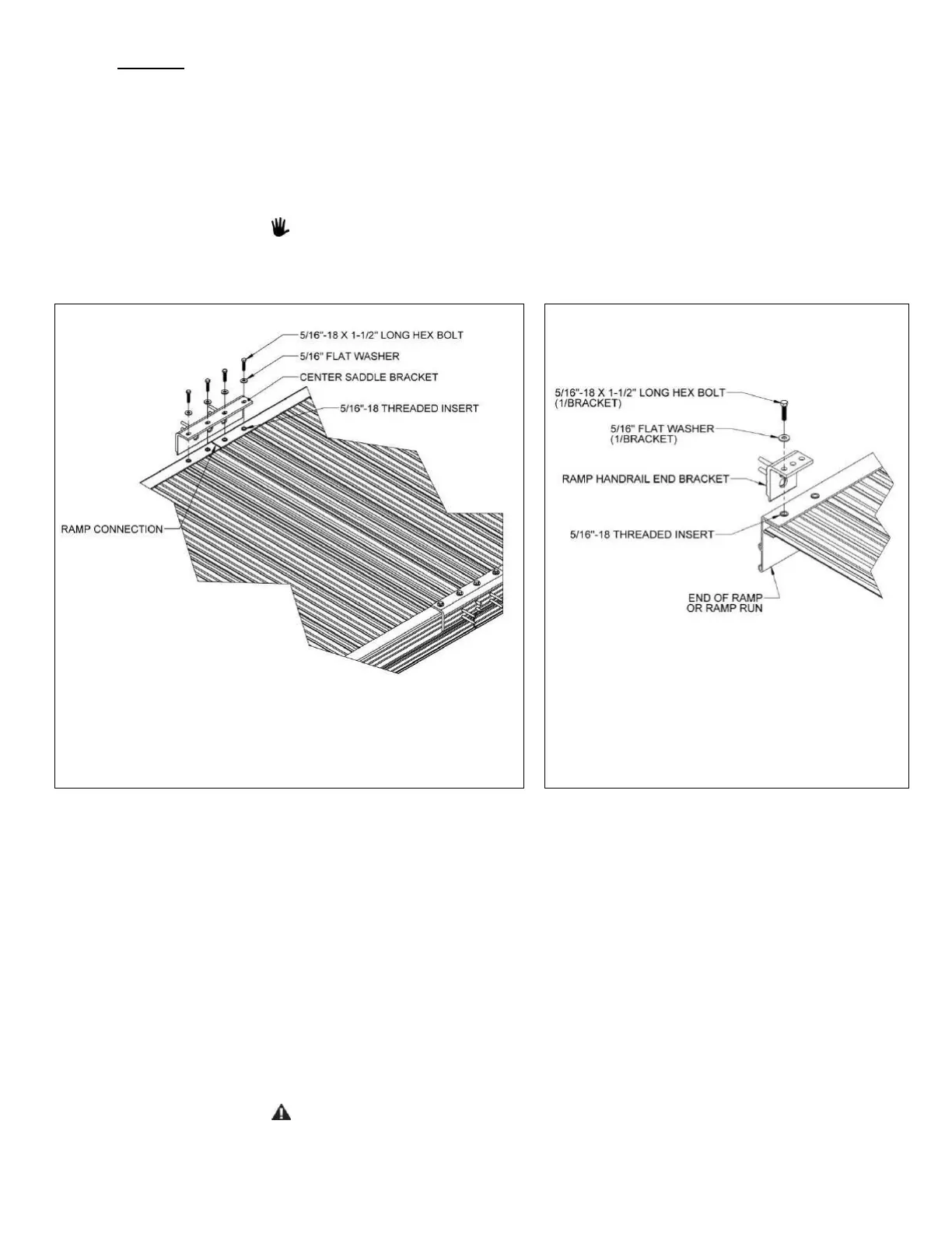
3.1.2. Butt the two sections together, end-to-end, ensuring there is no gap, then position the
two center saddle brackets, included in the
TRRC (CONNECTOR – RAMP TO RAMP
), over the
threaded inserts at the end of each ramp section (FIG. 3.1).
3.1.3. One edge of the center saddle bracket will slide into the groove of the ramp sections.
To create a run, ramp sections are connected using two interchangeable center
saddle brackets per joint. The center saddle brackets are also where the handrails
and ramp legs are attached.
3.1.4. Attach the center saddle brackets using four each 5/16″-18 x 1-1/2″ bolts and 5/16″
washers per bracket. Tighten all eight bolts (four each per center saddle bracket).
3.1.5. If you chose the TRST (RAMP SUPPORT) option, install as described in the ‘OPTIONAL
EQUIPMENT’ section.
3.1.6. Locate TRHBPR (RAMP HANDRAIL END BRACKET PAIR). Install four end brackets (these
will be used to attach handrails in a later step). Use one end bracket at each outside
corner of the ramp or ramp run using one 5/16″ x 1-1/2″ bolt and washer into the
threaded insert closest to the end of the ramp (FIG. 3.2).
3.1.7. Turn the joined ramps to their upright position, being careful not to damage the threaded
studs.
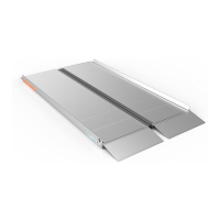
3.1.8. The starter ramp (see image in ‘BASIC SYSTEM COMPONENTS’ section) is the ramp with
the tapered section for transitioning to the ground and is generally the first ramp in the
system. It connects to the other ramps in the system in the same manner described in
this section.
The starter ramp is only intended for use with the tapered section completely
supported by the ground; do not use it in an elevated position.
 Loading...