Page 21 of 77
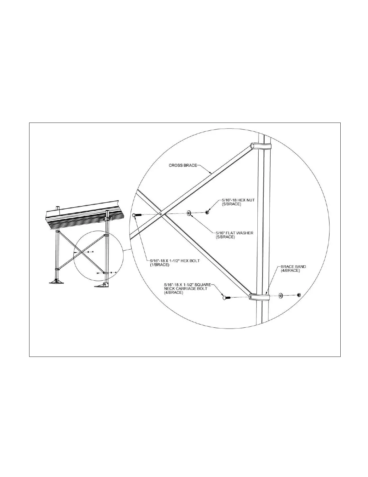
3.4. INSTALL CROSS BRACE - RAMPS
If the ramp walking surface is over 36″ high, a TXB36 (CROSS BRACE) must be installed under the
ramp (FIG. 3.10).
3.4.1. Separate ends of brace bands until they go around the support legs.
3.4.1.1. Install two bands on each leg with the part containing bolt holes
extending under the ramp and aligned with the brace bands on the
opposite side (FIG. 3.10).
3.4.2. The cross brace should be placed approximately in the middle of the ramp legs with the
top brace bands a minimum of two feet from the bottom brace bands.
3.4.3. Assemble the cross brace by installing the 5/16”-18 x 1-1/2” hex bolt, 5/16”-18 hex nut
and 5/16” flat washer through the center hole in the braces. Tighten enough to hold
the brace together but still allow it to pivot around the bolt (FIG. 3.10).
3.4.4. If needed for the location, trim the ends of the cross brace to fit.
3.4.5. Drill one 11/32” or 3/8” dia. hole on center approximately 1/2” from both ends of each
brace.
3.4.6. Install the assembled cross brace between the legs of the brace bands using the four
5/16”-18 x 1-1/2” long square neck carriage bolts, 5/16”-18 hex nuts, and 5/16” washers
provided (FIG. 3.10).
3.4.7. Tighten all fasteners securely.
 Loading...