Page 35 of 77
5. CLOSURES
Closures fill the space between ramp posts and platform posts. Like the ramp and platform handrails, they are
available in two-line rails and picketed guards. The closures come with components which require the ramp to
be mounted to one side or the other of a platform but the ramp can be centered or mounted in any location
on a platform side using the two-line rail closure (refer to SECTION 5.3). When centering or just off-centering
(mounting in a location other than the side) the ramp, a second two-line rail closure must be ordered and is
installed in the same manner as described below. When mounting to the side, the frame post should be
aligned with (or just slightly inside of) the inside of the platform angle post.
If the frame post is outside the platform angle post (are these the same item?), you will not be
able to install the end loops (refer to the ‘INSTALL RAMP HANDRAIL END LOOPS’ section).
The Two-Line Rail or Picketed Guard should be installed before installing the handrail or
connecting the frame top rail.
5.1. If installing a closure on a platform in the “straight” configuration, the 2” x 2” angle post will already be
in place; skip to SECTION 5.3.
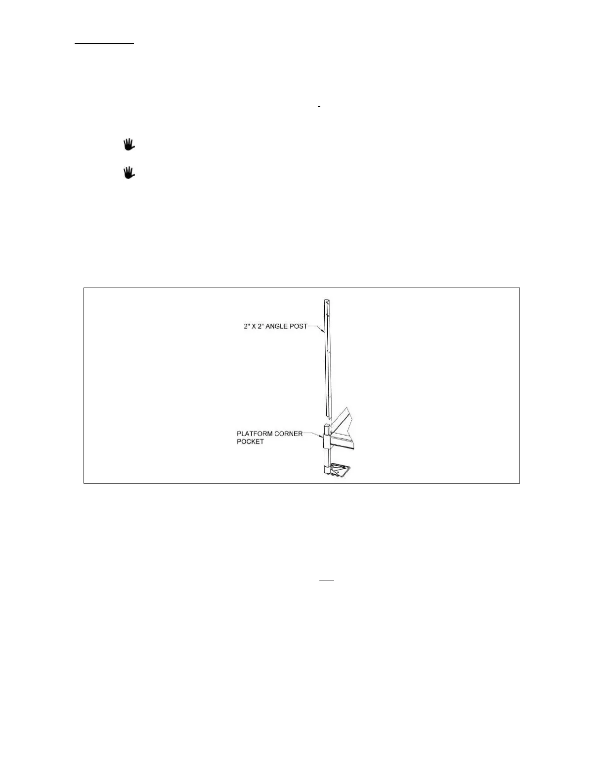
5.2. If installing a closure on a platform in the “turn” configuration, install the 2” x 2” angle post not
attached to a platform Two-Line Rail or Picketed Guard in the open platform corner pocket. Align the
bottom of the post with the bottom of the corner pocket and tighten the set screws securely (FIG. 5.1).
Refer to SECTION 4.6 for additional details on securing the post.
5.3. TWO-LINE RAIL BARRIER AND MIDRAILS
5.3.1. The 1.5” x 2” barrier will come in the length required for the platform side and should not
need to be trimmed. Insert 1-1/2” square threaded inserts into both ends of the barrier.
Use a rubber mallet or similar tool to fully seat the threaded inserts as needed (FIG. 5.2).
5.3.2. Attach the lower 1.5” x 2” barrier to the lowermost hole in the 2” x 2” angle post using
a 5/16”-18 x 1” long hex bolt (do not use a flat washer at this location). The 1.5” x 2”
barrier is commonly installed with the larger cavity (into which the 1-1/2” square
threaded insert is inserted) on top and the smaller cavity on the bottom (FIG. 5.2).
5.3.3. Locate the appropriate barrier attachment plate. If the upper end of the ramp or ramp
run terminates at a platform use the “up sloping” version of the plate. If the lower end of
a ramp or ramp run starts at a platform use the “down sloping” version. Note the
orientation of the larger 3/8” diameter hole with respect to the 1-1/2” x 2” section of the
plate as shown (FIG. 5.3) to identify the barrier attachment plate needed.
 Loading...