Page 58 of 77
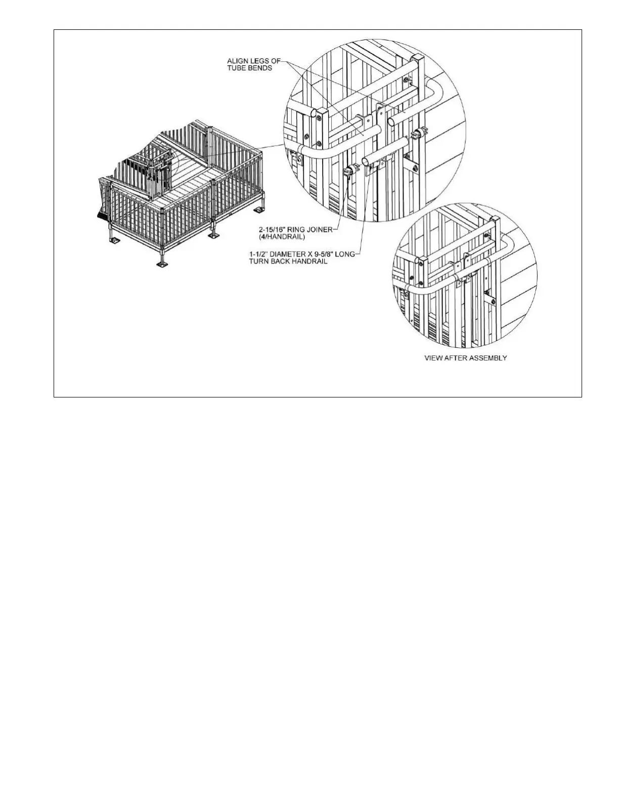
5.8.9. Locate the special turn back handrail and the 1-1/2” diameter x 9-5/8” long tube with
two welded brackets.
5.8.10. Insert 2-15/16” ring joiners into both ends. Orient the joiner set screw toward the
brackets on the underside and tighten the joiner set screws securely (FIG. 5.34).
5.8.11. Loosen the tube bend assembly screws and align the long leg of the 1-1/2” diameter
tube bends, then tighten the elbow assembly screws and joiner set screws enough to
hold the components in position. Hold the turn back handrail under the 1-1/2”
diameter tube bends to assist in the alignment. It will be necessary to trim the short leg
of one of the tube bends to align properly. Remove and reinstall the tube bends as
needed (FIG. 5.34).
5.8.12. Once the 1-1/2” diameter tube bends have been aligned, use the turn back handrail
with the ring joiners installed to mark the tube bends for trimming (FIG. 5.34).
5.8.13. Cut the 1-1/2″ diameter tube bends at the marked locations. Using a metal file, smooth
any sharp edges from cutting.
5.8.14. Install the cut 1-1/2″ diameter tube bends onto the 2-15/16” ring joiners installed in
the turn back handrail (FIG. 5.34).
5.8.15. Align the short legs of the tube bends with the 2-15/16” ring joiners installed in Ramp
Handrails and install the assembly onto the joiners. Tighten all ring joiner set screws
securely.
5.8.16. Use the holes in the handrail brackets welded to the turn back handrail as a template
to drill 5/16” or 11/32” holes through the 2” x 2” turn back angle posts.
 Loading...