Page 61 of 77
5.9.3. Connect the Frame top rails at the corner turn by inserting 2-15/16” ring joiners in the
open ends of the Frame top rails and adjustable elbows on the opposite end of the ring
joiners. Install 2-15/16” ring joiners into the other ends of the elbows. Orient the joiner
set screw toward the underside and the legs of the adjustable elbows, toward the 2” x 2”
angle post in the corner, then tighten the joiner set screws and the adjustable elbow
assembly screws enough to hold in place (FIG. 5.37).
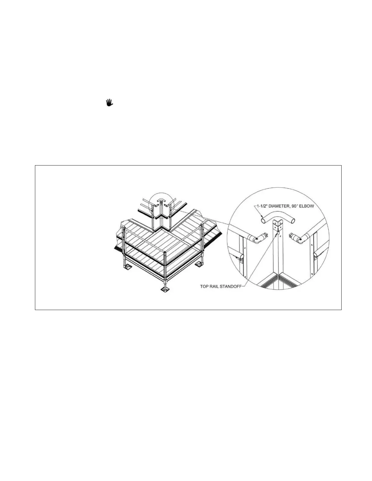
5.9.4. Clamp the Top Rail Standoff to the 2” x 2” angle post in the corner at 1-1/2” from the top
of the post. Hold a 1-1/2” diameter, 90° elbow such that the middle of the bend is
centered on top of the Top Rail Standoff. Rotate the adjustable elbows with the joiners
until they are parallel, as shown (FIG. 5.38).
There are two standoffs used at the corner turn post. The Top Rail Standoff is the
smaller, shorter one of the two.
5.9.5. Mark the 1-1/2” diameter, 90° elbow at the ends of the ring joiners and trim at the
marked locations. Using a metal file, smooth all sharp edges from cutting.
5.9.6. Install the 1-1/2” diameter, 90° elbow between the joiners. Remove and reinstall the
adjustable elbows and ring joiners, then tighten all joiner set screws and elbow assembly
screws securely.
 Loading...