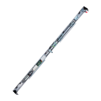
A1400 AIR 119 532129 04 - Rev.B
Vp Lt B I C D
800 1700 585 1292 250 2744
900 1900 685 1344 380 2848
1000 2100 785 1400 510 2960
1100 2300 885 1456 640 3072
1200 2500 1035 1340 935 2840
1300 2700 1085 1440 1035 3040
1400 2900 1185 1540 1135 3240
1500 3100 1285 1640 1235 3440
1600 3300 1385 1740 1335 3640
1700 3500 1485 1840 1435 3840
1800 3700 1585 1940 1535 4040
1900 3900 1685 2040 1635 4240
Vp Lt B I C D
2000 4100 1785 2140 1735 4440
2100 4300 1885 2240 1835 4640
2200 4500 1985 2340 1935 4840
2300 4700 2085 2440 2035 5040
2400 4900 2185 2540 2135 5240
2500 5100 2285 2640 2235 5440
2600 5300 2385 2740 2335 5640
2700 5500 2485 2840 2435 5840
2800 5700 2585 2940 2535 6040
2900 5900 2685 3040 2635 6240
3000 6100 2785 3140 2735 6440
C
I
Lt
B
Vp
130
Lt = Vp X 2 + 100
Translation of the original instructions
ENGLISH
24.3 POSITION OF COMPONENTS ON A1400 AIR DM SUPPORT PROFILE
A1400 AIR DM RIGHT OPENING SINGLE LEAF
121
Motor 2
Motor 1
Control
board
Power supply
Emergency
batteries
B = Carriage fixing distance on the sliding leaf
C = Motor position
D = Transmission belt length
I = Motor / transmission unit centre distance
Lt = Head section length
Vp = Free passage opening
100 = leaf overlap (mm)

 Loading...