1
2
3
2 cm
12-24 V
AC-DC
COM
NC
NO
COM
NO
NC
NO NC
*
*
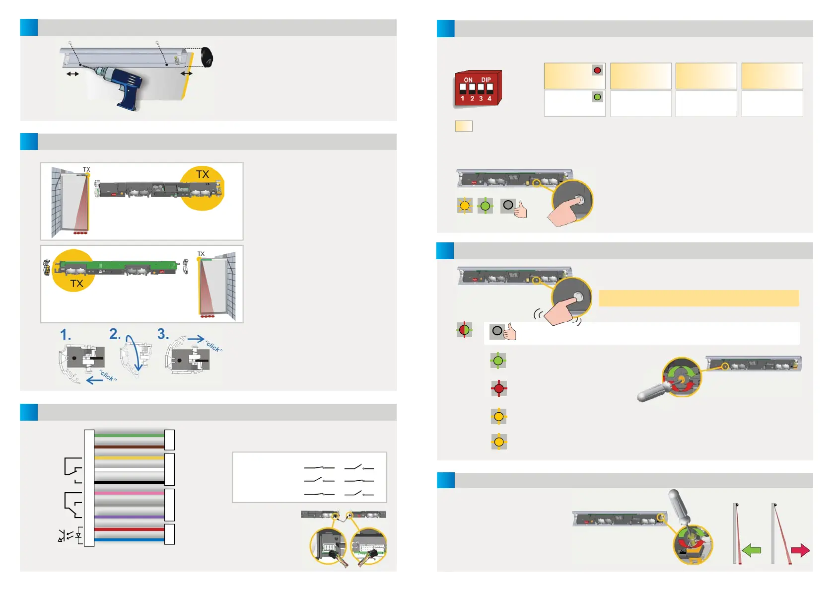
MOUNTING THE PROFILE
POSITIONING THE MODULES
WIRING
GREEN
BROWN
YELLOW
WHITE
BLACK
PINK
GREY
VIOLET
RED**
BLUE**
POWER SUPPLY
STOP IMPULSE
OPENING SIDE
REVERSE IMPULSE
CLOSING SIDE
TEST OUPTUT***
The transmitter (TX) should be placed
next to the door edges that need to be
protected.
The angle adjustment clip should be
next to the transmitter.
Turn the module if necessary.
When a module needs to be turned:
1. detach the clips
2. turn them by 180°
3. reattach
NO POWER
NO DETECTION
DETECTION
The module connected to the door
controller becomes the MASTER.
Plug the SLAVE
CABLE between
the modules in
one of the two
placements.
Mount the profi les as close as possible
to the closing edge.
Leave 2 cm for the black end caps.
Take the position of the white clips
into account before drilling and
fastening the screws.
* Output status when sensor is operational
** For compliance with DIN 18650, connection to door controller test output is required.
*** If door controller is not tested: conncect BLUE to 0 V and RED to +12 V - 30 V DC.
4
6
5
4
5
X
SETTINGS
DOOR SAFETY CHECK
CALIBRATION
IMPORTANT: Test the good
functioning of the installation
before leaving the premises.
If necessary, position spots
closer to or away from the door
and relaunch a calibration.
After changing a DIP-switch, the orange LED fl ashes.
A LONG push on the push button of the MASTER
confi rms the settings of ALL MODULES.
Afterwards, a number of green fl ashes (x) indicates
the number of connected modules
.
A SHORT push on the button of the MASTER launches a
calibration on ALL MODULES.
Do not stand in the detection fi eld!
When the LED is off on all modules, the detection zone is OK.
The detection zone is too short:
turn the screw clockwise.
The detection zone is too long:
turn the screw anticlockwise.
Step out of the detection fi eld.
If necessary, change angle or switch off background (DIP 3 = OFF).
Launch a new calibration.
The fl ashing speed of the LED
increases when approaching
the optimal position.
MOUNTING
SIDE
FREQUENCY BACKGROUND
UNCOVERED
ZONE
RELAY 1
OPENING SIDE
RELAY 2
CLOSING SIDE
FREQ A
FREQ B
ON
OFF
35 cm*
15 cm
ON
OFF
LED during detection:
R1 > RED
R2 > GREEN
Set different
frequencies on
modules close to
each other.
Not enough background
refl ectivity: switch to OFF
Mounting height > 2.7 m:
switch to ON to allow for
DIN 18650-conformity
Approximate values
at 1.8 m.
* Recommended for
most applications
RED-GREEN
OFF
GREEN
RED
ORANGE
ORANGE GREEN OFF
FACTORY VALUE
 Loading...