EasyManua.ls Logo

FabiaTech FB2510 Series - User Manual

FabiaTech FB2510 Series
3 pages
Print Icon
To Next Page IconTo Next Page
Loading...
Version 1.5
FB2510 Series User’s Quick Setting
Page 1/3
©2001-2003 FabiaTech Corp.
1. Brief
The FB2510 is an all-in-one, PC/104, NS Geode low power CPU module. This user’s quick setting
provides the jumper settings, connector location, and their pin assignment.
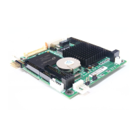
2. Board Placement
CN3
CN9
CN6
J5J4 JP1
CN7
BUS1
CN5
CN1
J3
CN2
J6
CN8
CN4
J1 J2
LED1
J7
3. Packing List
1 FB2510x all-in-one PC/104 CPU board.
1 VGA (CRT interface) adapter cable.
1 44-pin hard disk drive interface cable.
1 20-pin to 34-pin floppy drive interface cable.
2 serial port adapter cable and 1 parallel port interface cable.
1 PS/2 keyboard and mouse port adapter cable.
1 USB adapter cable. (Optional)
1 10-pin LAN adapter cable with FB4605A transfer board.
1 compact disc includes software utility.
1 hard copies of this quick setup manual.
4. Features
* On-board 200~300 MHz NS Geode GX1 CPU.
* NS CS5530A chipset with UMA architecture.
* 1 So-DIMM socket for up to 128MB PC-100 SDRAM.
* One 100/10 base-T Ethernet port.
* Provides CRT and LCD with 1.5MB to 4MB shared memory.
* 1 parallel port, 2 RS-232, 1 floppy port and 1 PCI IDE interface.
* PS/2 compatible keyboard and mouse interface.
* Provides header for external speaker and hard disk access LED.
* Flash BIOS with easy upgrade utility.
* 2 USB ports and software programmable watchdog timer.
* Power requires +5V only, 1.2A maximum.
* PC/104 form factor, 90.2 mm x 95.9 mm (3.55” x 3.775”)
5. Connectors, Headers and Their Relative Jumpers
A. Reset Header (J5)
J5 is a 2-pin header for connecting to system reset bottom. Close these 2 pins to hardware reset
FB2510 and restart system booting.
B. Power Connector (J4: 4-pin 2.5mm JST)
C. Keyboard and Mouse Connector (CN9)
CN9 provides PS/2 keyboard and mouse interface, use the included adapter cable to connect
between CN9 and standard PS/2 device.
D. IDE Hard Disk Connector and Access LED Header (CN4 and J7)
Use 44-pin hard disk cable you can attach up to two 2.5” hard disk drives.
Pin 1: Mouse Data
Pin 2: Keyboard Data
Pin 3: Ground
Pin 4: +5V
Pin 5: Mouse Clock
Pin 6: Keyboard Clock
6
1
CN9
J4
Pin 1: +5V
Pin 2: Ground
Pin 3: Ground
Pin 4: +12V
14
Note: FB2510 needs +5V only,
+12V is not necessary.
1
2
J7
Pin 1: LED+
Pin 2: LED-
Question and Answer IconNeed help?

Do you have a question about the FabiaTech FB2510 Series and is the answer not in the manual?

Overview

The FB2510 Series is an all-in-one, PC/104, NS Geode low power CPU module designed for embedded applications. This quick setting guide provides essential information regarding its functions, technical specifications, usage features, and maintenance aspects.

Function Description

The FB2510 serves as a compact and versatile CPU module, integrating various functionalities required for embedded systems. It supports a range of peripherals and interfaces, making it suitable for diverse applications. The module's design emphasizes low power consumption, which is characteristic of the NS Geode GX1 CPU. It provides core computing capabilities, memory support, and a comprehensive set of I/O interfaces, including display, storage, networking, and serial communication.

Important Technical Specifications

CPU and Chipset:

  • On-board 200-300 MHz NS Geode GX1 CPU.
  • NS CS5530A chipset with UMA (Unified Memory Architecture).

Memory:

  • 1 SO-DIMM socket for up to 128MB PC-100 SDRAM.

Display:

  • Provides CRT and LCD support with 1.5MB to 4MB shared memory.
  • CN2 is an 18-bit LCD interface connector.
  • CN1 provides control signals and power source for the LCD inverter.
    • CN1 Pin 1: +12V
    • CN1 Pin 2: Ground
    • CN1 Pin 3: ENABLK
    • CN1 Pin 4: N.C.
    • CN1 Pin 5: +5V
    • Note: +12V is sourced from J4 (power connector) only.
  • CN3 is the CRT connector, supporting D-sub 15-pin.
    • Pin 1: RED
    • Pin 3: GREEN
    • Pin 5: BLUE
    • Pin 7: VSYNC
    • Pin 9: HSYNC
    • Pin 2: Case Ground
    • Pin 4: Digital Ground
    • Pin 6: Analog Ground
    • Pin 8: DDC Data
    • Pin 10: DDC Clock

Storage and I/O:

  • 1 parallel port.
  • 2 RS-232 serial ports (CN6 & CN8).
  • 1 floppy port (CN5: 20-pin 2.0mm IDC).
  • 1 PCI IDE interface (CN4).
  • PS/2 compatible keyboard and mouse interface (CN9).
  • 2 USB ports (J3).
  • 1 10/100 base-T Ethernet port (J1).

Power:

  • Requires +5V only, 1.2A maximum.
  • J4 is the 4-pin 2.5mm JST power connector.
    • Pin 1: +5V
    • Pin 2: Ground
    • Pin 3: Ground
    • Pin 4: +12V (Note: +12V is not necessary for FB2510 operation).

Physical Form Factor:

  • PC/104 form factor: 90.2 mm x 95.9 mm (3.55" x 3.775").

BIOS:

  • Flash BIOS with easy upgrade utility.

Other Features:

  • Software programmable watchdog timer.
  • Header for external speaker (J2) and hard disk access LED (J7).

Usage Features

Connectivity:

  • Floppy Drive: The included 20-pin to 34-pin floppy drive interface cable supports 720KB, 1.44MB, and 2.88MB floppy disk drives. It does not support 360KB and 1.2MB drives.
  • Parallel Port: A 26-pin to DB-25 printer interface cable is provided for the parallel port (CN7).
  • Serial Ports: Serial port cables are used to connect CN6 and CN8 to 9-pin D-type male connectors.
  • Keyboard and Mouse: CN9 provides a PS/2 interface. An adapter cable is included to connect to standard PS/2 devices.
  • IDE Hard Disk: A 44-pin hard disk cable allows connection of up to two 2.5" hard disk drives to CN4.
  • USB: The optional USB adapter cable (J3) allows connection of up to two USB devices.
  • LAN: J1 provides twist-pair signals for the LAN port. An adapter board (FB4605A) with a cable is used to transfer to a standard RJ45 connector. The FB4605A board also features LEDs: an orange LED for data access and a green LED for on-line status.
  • PC/104 Connectors: BUS1 (64-pin IDC & 40-pin IDC) provides standard PC/104 expansion capabilities.

System Control:

  • Reset Header (J5): A 2-pin header for connecting to a system reset button. Closing these pins performs a hardware reset and restarts system booting.
  • External Battery Header (J6) and Battery Select Jumper (JP1): J6 is used to connect an external battery pack if the on-board Lithium battery is depleted. JP1 must be set correctly for either on-board or external battery usage. The factory preset is for on-board battery.
    • JP1 (1-2 closed): On-Board Battery
    • JP1 (2-3 closed): External Battery
    • Note: External battery voltage should be 2.6V to 3.6V.

Indicators:

  • Hard Disk Access LED (J7): A header for an external hard disk access LED.
  • Power/Watchdog LED (LED1): This LED indicates power-on when lit. When blinking, it signifies that the watchdog timer is enabled. The watchdog is disabled, and the LED remains continuously lit after a system reset.

Maintenance Features

  • Flash BIOS: The Flash BIOS allows for easy upgrades, facilitating system maintenance and feature enhancements.
  • Technical Support: In case of any issues connecting the FB2510 with LCD panels, users are advised to contact the technical support division of FabiaTech Corporation.
  • Battery Management: The provision for an external battery pack (J6) ensures continued operation even if the on-board Lithium battery is depleted, offering flexibility in power management and maintenance. The correct setting of JP1 is crucial for proper battery operation.
  • Watchdog Timer: The software programmable watchdog timer can be used to monitor system operation and automatically reset the system in case of software hangs, enhancing system reliability and reducing the need for manual intervention.

FabiaTech FB2510 Series Specifications

General IconGeneral
BrandFabiaTech
ModelFB2510 Series
CategoryComputer Hardware
LanguageEnglish