2
RADIO RECEIVER EXTERNAL TYPE. ENCODING INSTRUCTIONS AND W ORKING PRINCIPLE
LED
2
nd
PUSH
BUTTON
TRANSMITTER
JUBI-SM ALL•433
2 CHANNELS
TRANSMITTER
JUBI•433
4 CHANNELS
LED
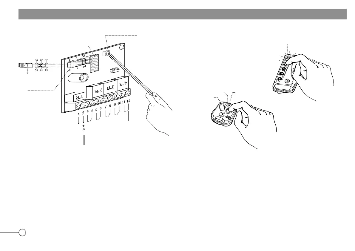
ANY BUTTON IN THE TRANSM ITTER CAN BE PRESSED TO OPERTE ANY REQUIRED CHANNEL, PROVIDED THAT THE “ STRIP” IS INSERTED IN THE PROPER “ PIN” CONNECTORS
THAT CORRESPOND TO THE DESIRED CHANNEL. ENCODE THE UNIT AS DESCRIBED.
The instructions that follow explain how to set a personalized code (ie. user’s code) with any one receiver. First supply 24 Volt a.c. pow er to terminals 1 (–) and 2 (+) in the
receiver terminal board - then insert the “ STRIP” as in position “C1” . This activates the relay “ 1R” that corresponds to terminals 3 and 4 (CHANNEL No. 1). The next step is
to press simultaneously the switch button “ P” on the receiver PC board and the switch button “ T” (any desired one) on the transmitter for about five seconds. Once the code
has been memorized by the unit, the “ LED” on the receiver PC board sw itches on. Release the transmitter button and the receiver switch button; remove the “ STRIP” jumper
and insert it on to a “ PIN” connector on standby. Now the radio remote control set has been encoded with a personalized, secret code and is ready to work. Repeat the above
sequence for channels 2-3-4. Insert the “ STRIP” jumper in the correct position as required, as follows:
Position “ C2“ . It corresponds to relay No. 2 (2R) - Channel No. 2. - Terminals 5-6
Position “ C3“ . It corresponds to relay No. 3 (3R) - Channel No. 3. - Terminals 7-8
Position “ C4“ . It corresponds to relay No. 4 (4R) - Channel No. 4. - Terminals 9-10
SHOULD THE POWER SUPPLY FAIL OR THE 24 V a.c. - 12 Vd.c. BE DISCONNECTED FROM THE RECEIVER, THE USER’S CODE IS RETAINED IN THE REMOVABLE M EM ORY THAT
CAN BE FITTED ON TO ANOTHER CARD.
Drw g. No. 3706
RECEIVER FOR EXTERNAL APPLICATION
AERIAL
REM OVABLE
M EM ORY
CHANNEL 1
SWITCH BUTTON “ P“
“ STRIP“
JUM PER
24 V a.c.
POWER SUPPLY
PIN
CHANNEL 4
CHANNEL 3
CHANNEL 2
–
1
st
PUSH
BUTTON


 To Next Page
 Loading...

