Maximize Performance And Life
The performance and life of couplings depend largely upon
how you install and maintain them. Before installing couplings,
make certain that foundations of equipment to be connected
meet manufacturers’ requirements. Check for soft foot. The use
of stainless steel shims is recommended. Measuring
misalignment and positioning equipment within alignment
tolerances is simplified with an alignment computer. These
calculations can also be done graphically or mathematically.
Alignment is shown using spacer bar and straight edge. This
practice has proven to be adequate for many industrial
applications. However, for superior final alignment, the use of
dial indicators (see Manual 458-834 for instructions), lasers,
alignment computers or graphical analysis is recommended.
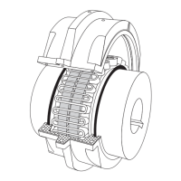
1— Mount Seals And Hubs
Lock out starting switch of prime mover. Clean all metal parts
using a non-flammable solvent. Lightly coat seals with grease
and place on shafts BEFORE mounting hubs. Heat hubs as
previously instructed. Seal keyways to prevent leakage. Mount
hubs on their respective shafts so the hub face is flush with the
end of its shaft unless otherwise indicated.
2 — Gap and Angular Alignment
Use a spacer bar equal in thickness to the gap specified in
Table 2, Page 5. Insert bar as shown above, to same depth at
90° intervals and measure clearance between bar and hub
face with feelers. The difference in minimum and maximum
measurements must not exceed the ANGULAR INSTALLATION
limits specified in Table 2.
3 — Offset Alignment
Align so that a straight edge rests squarely (or within the limits
specified in Table 2) on both hubs as shown above and also at
90° intervals. Check with feelers. The clearance must not
exceed the PARALLEL OFFSET installation limits specified in
Table 2. Tighten all foundation bolts and repeat Steps 2 and 3.
Realign coupling if necessary. NOTE: Use a dial indicator for
more accurate alignment.
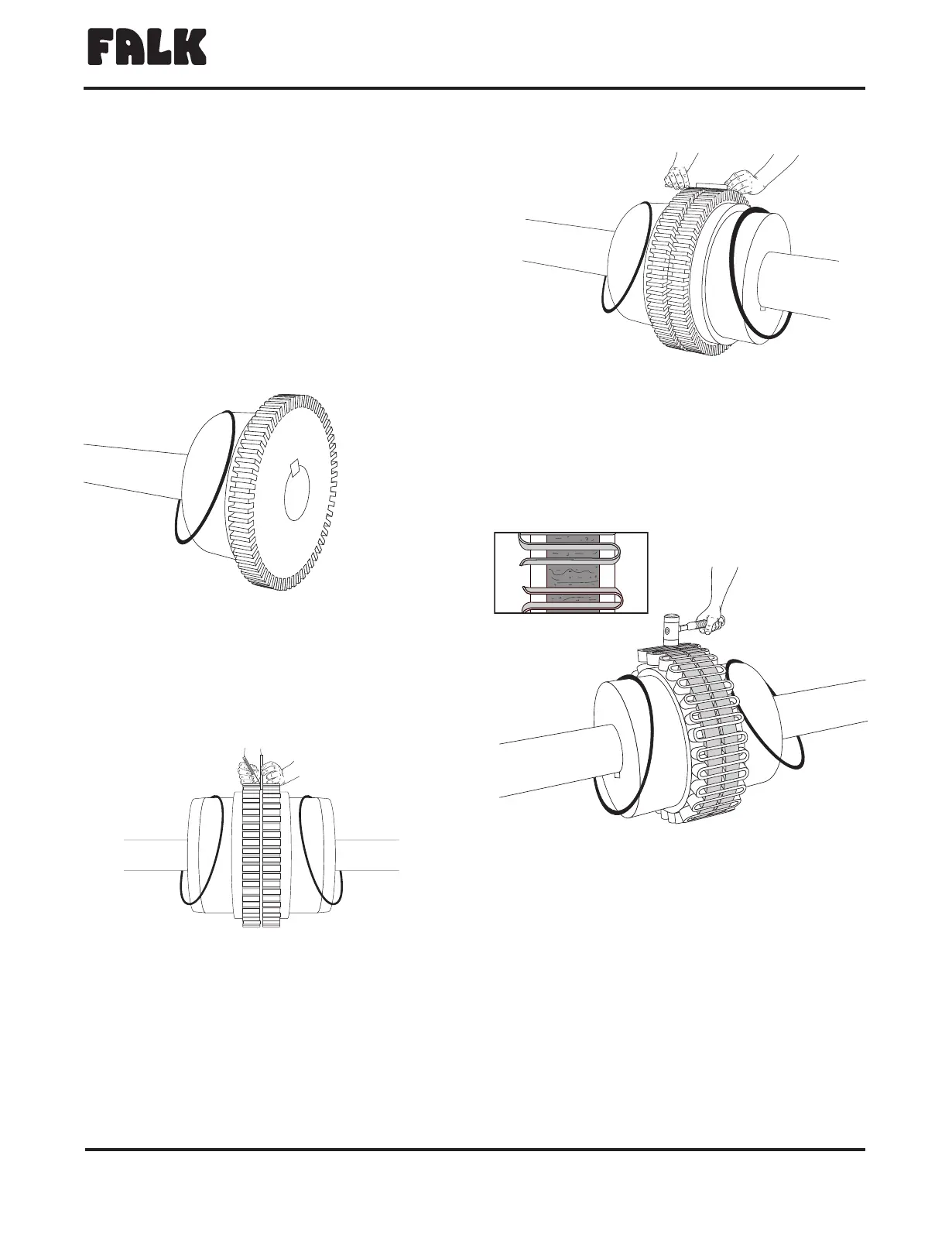
4 — Insert Grid
Pack gap and grooves with specified lubricant before inserting
grid. When grids are furnished in two or more segments, install
them so that all cut ends extend in the same direction (as detailed
in the exploded view picture above); this will assure correct grid
contact with non-rotating pin in cover halves. Spread the grid
slightly to pass over the coupling teeth and seat with a soft mallet.
®
The Falk Corporation, P.O. Box 492, Zip 53201-0492 428-112
3001 W. Canal St., Zip 53208-4200, Milwaukee, WI USA Telephone: 414-342-3131 May 2000
Fax: 414-937-4359 e-mail: falkinfo@falkcorp.com web: www.falkcorp.com Supersedes 12-98
Steelflex
®
Couplings
•
Installation and Maintenance
Type T10
•
Sizes 1150–1260 & 150–260 (Page 3 of 6)
MOUNT
SEAL
FIRST
 Loading...