Gate control
CV's:
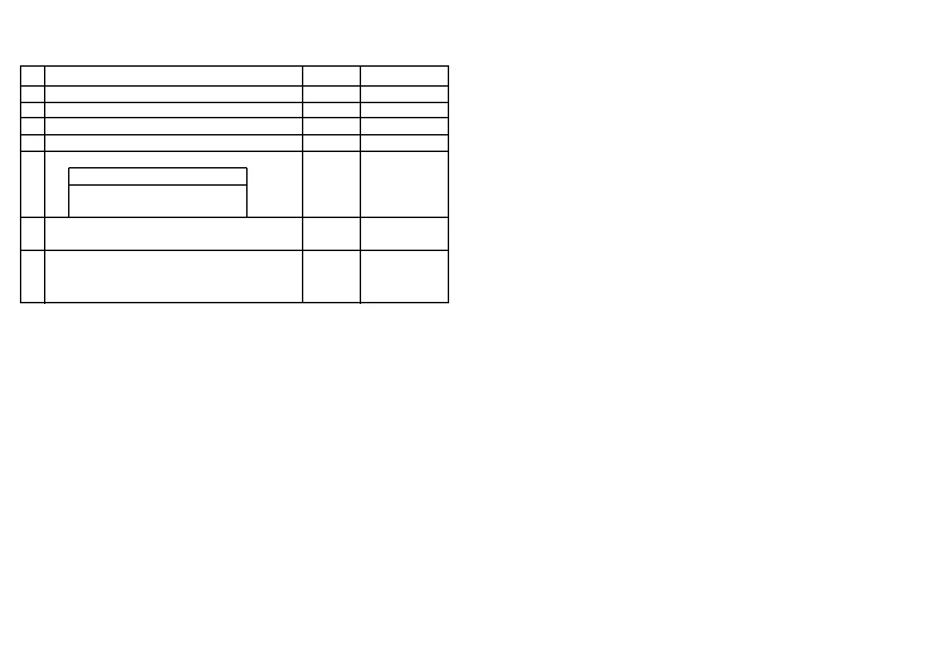
CV Legend Default Range of values
7 Software Version 1-
8 Manufacturer identifier 85 -
47 HighByte address 0 1-255
48 LowByte address address = CV47*256 + CV48 1 1-255
49 Configuration: 0 1-255
Bit 7 0=DCC 1=Mot
Bit 0 =0 -> automatic
=1 -> non-automatic
50 Blinker time constant 67 1-255
Value * 10ms = On/off time
51 Fade time constant 5 1-255
Cross fading time from light to dark and vice versa
= Value * 200us * 256
The LED flashing frequency can be adjusted with the CV50. The value in the CV determines the LED
on/off time, namely:
on or off time = CV value * 10ms
The fade times for exits J111 and J112 can be adjusted with the CV51, namely:
Fade time = value * 200us * 256
The data format for digital operation and the digital operating mode is stored in CV49.
for CV49:
DCC: operating modes: automatic CV49=0
non-automatic CV49=1
Motorola: operating modes: automatic CV49=128
non-automatic CV49=129
Notice for CV49: Do not use other values! If CV49 was set to 128 or 129,
the controls will now only respond to the Motorola data format and can only be reversed
to DCC mode through key programming.
General notices:
All CVs can only be programmed via DCC digital command station connected to the programming
track output.
Notice for CV8:
Programming any value in CV8 will reset all CVs to their factory defaults.
Function:
Start contact:
----------------
The start contact always starts automatic operation, regardless of the
status of the control at the time the contact is closed.
Digital operation:
---------------------
Digital mode 1: (CV49-Bit0=0)
A digital point command »red« corresponds to the start contact and triggers
the automatics. The respective point command »green« will be ignored.
Digital mode 2: (CV49-Bit0=1)
A digital point signal »red« closes the gate.
A digital gate signal »green« opens the gate.
Programming the key button:
-------------------------------------
The programming key button can only be used in idle mode
(gate up, LED and stop point off)!
1.) Press key button -> LED will blink 3x
2.) Now operate a point on a Motorola centre the LED will blink 3x, the address has been accepted.
The control system is set to Motorola data format.
When using a DCC station:
3.) Press key button again -> LED will blink 3x
4.) Now operate a point on a DCC station the LED will blink 3x, the address has been accepted.
The control system is set to DCC data format.
If no entry is to be made:
5.) Press key button again -> the LED will blink 3x The control system is returned to working mode.
Important:
-------------
If the control system was set to Motorola via key programming,
it cannot be programmed and read with a DCC programming
track. To return the control system from Motorola data format to
DCC data format, the control system must first be changed to DCC mode
via key programming.
Protecting the motor end stage and the stopping outputs:
------------------------------------------------------------------------
Rapid blinking LED -> motor output short circuit
LED blinks same as during programming -> stop point short circuit
18
 Loading...