4’
-5’
-6’
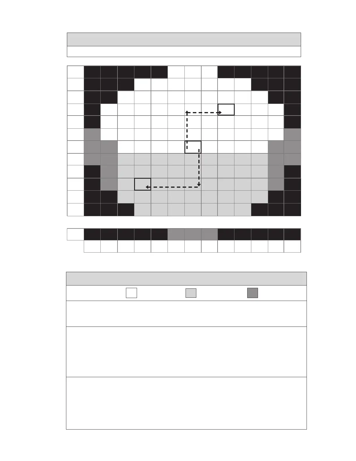
Getting Started:
Locate the center 0’ cell shown above at the intersection of the X and Y axes; this
represents the location of the Dorsal D-Ring on the User’s FBH.
Overhead (above the Dorsal D-Ring) Starting at the center 0’ cell, follow the arrows:
EXAMPLE: With leg-end snap hook connected to the Dorsal D-ring on FBH, User installs a
6’ SRD unit 3’ overhead (up the Y axis) and 2’ laterally (along the X axis).
This intersection shows 1’ of additional Fall Clearance needed which is caused by Swing
Fall.
This additional 1’ must be added to the MRFC for Overhead Use shown in Figure 3A.
Non-Overhead (below the Dorsal D-Ring) Starting at the 0’ cell, follow the arrows:
EXAMPLE: With leg-end snap hook connected to the Dorsal D-ring on FBH, User installs the
6’ SRD unit 3’ below the dorsal d-ring (down the Y axis) and 3’ laterally (along the X axis).
This intersection shows 3’ of additional Fall Clearance needed which is caused by Swing Fall.
This additional 3’ must be added to the MRFC for Non-Overhead Use in Figure 3B.
T6SRD13
Using Chart 1 for Addional Fall Clearance
Chart 1: Addional Required Fall Clearance Due to Swing Fall ()
C6SRD13
6’
-3’
6’
6’
6’
6’
6’
6’
6’
6’
5’
6’
6’
Y-Axis: Locaon of Aachment Point Relave to Dorsal D-Ring on FBH ()
Any Connection More than 5’ Below User’s Dorsal D-Ring is Not Allowed
2’
4’
0’
5’
-4’
1’
3’
-1’
-2’
6’
1’
3’
1’
3’
2’
3’
2’
1’
1’
0’
1’
0’
1’
0’
1’
0’
1’
0’
0’
1’
6’
2’
0’
2’
0’
2’
1’
2’
1’
1’
1’
6’
2’
0’
2’
0’
2’
1’
2’
1’
1’
1’
6’
5’
6’
6’
6’
6’
3’
5’
4’
3’
3’
0’
1’
0’
1’
0’
1’
0’
1’
0’
0’
1
6’
3’
1’
3’
1’
3’
1’
2’
3’
2’
6’
5’
6’
6’
6’
6’
3’
5’
4’
3’
3’
6’
6’
4’
2’
2’
2’
4’
3’
2’
2’
0’
0’
0’
0’
0’
0’
0’
0’
0’
0’
0’
0’
0’
6’
4’
6’
4’
2’
2’
2’
4’
3’
2’
2’
6’
6’
6’
6’
6’
6’
6’
6’
6’
6’
6’
3’
3’
3’
1’
1’
1’
2’
2’
2’
2’
2’
2’
5’
5’
5’
1’
1’
1’
3’
3’
3’
5’
5’
5’
4’
4’
4’
4’
4’
6’
6’
6’
5’
6’
6’
= Allowable Use AreaKey to Work Zone Areas:
= Cautionary Use Area
= Not Allowed Use Area
1’
0’
X-Axis: Lateral Work Zone ()
Limited to 310 lb Max User Weight
4’
3’
APPENDIX A
010819
 Loading...