3
Part #???
Revised ??????
FAST™
3400 Democrat Rd.
Memphis, TN 38118
Phone: (901) 260-3278 Fax: (901) 366-1807
www.fuelairspark.com
Part # FAST4-160
Revised 11/30/09
FAST™
3400 Democrat Rd.
Memphis, TN 38118
Phone: (901) 260-3278 Fax: (901) 375-3408
www.fuelairspark.com
DIP Switch (5-6)
[0=OFF, 1=ON]
# of
Cylinders
DIP Switch (7)
[0=OFF, 1=ON]
Operation
Mode
DIP Switch (8)
[0=OFF, 1=ON] Coil Layout
0 - 0 2 Cylinder 1 Standalone 1 Coil per Cylinder
1 - 0 4 Cylinder 0 CAN Enabled 0 Waste Spark
0 - 1 6 Cylinder
1 - 1 8 Cylinder
“CAN Enabled” allows XIM™ to
communicate with XFI™
“Waste Spark” – Each coil fires two
companion cylinders simultaneously.
SW2 / SW3 / SW4 / SW5 (rotaries with detents)
SW2, SW3 and SW5 settings are only required for Onboard mode. They are not used with the optional Remote
or PC software.
Setting Resolution
Min
(position 0)
Max
(position 9)
SW3
Idle timing (°BTDC) 2 6 24
SW2
Max timing (°BTDC) 2 22 40
SW5
All in (RPM) 200 1800 3600
SW4*
Rev Limit 1000's
(RPM) 1000
(position 3)
3000 9000
* SW4 is also used to select between the three modes of Standalone operation. It is set to 0 for PC Software
mode, 1 for Remote mode, or 3-9 for Onboard mode.
SW3 SW2 SW5 SW4*
Switch
Position
Idle Timing
(°BTDC)
Max timing
(°BTDC)
All in
(RPM)
Standalone
Mode
Rev Limit
1000’s (RPM)
0
6 22 1800 PC Software n/a
1
8 24 2000 Remote n/a
2
10 26 2200 n/a n/a
3
12 28 2400 Onboard 3000
4
14 30 2600 Onboard 4000
5
16 32 2800 Onboard 5000
6
18 34 3000 Onboard 6000
7
20 36 3200 Onboard 7000
8
22 38 3400 Onboard 8000
9
24 40 3600 Onboard 9000
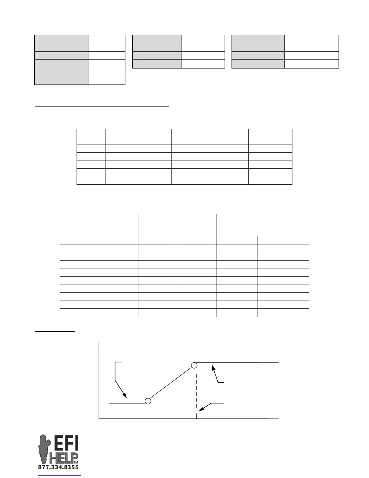
Timing Curve
SW2, SW3 & SW5 are used to construct a base timing curve.
.
RPM
SW2: Max Timing
1250
Ignition Timing
SW3: Idle Timing
SW5: All-in RPM
 Loading...