3
Part #FAST4-101
Revised 7/9/07
FAST™
3400 Democrat Rd.
Memphis, TN 38118
Phone: (901) 260-3278 Fax: (901) 375-3408
www.fuelairspark.com
BLOCK GND:
This wire is to be connected to a good paint and rust free ground source on the engine block of your
vehicle. It is only used for the LS1/LS2/LS6/LS7 engines and will not be found in other harnesses.
DRIVER COILS:
This connector plugs into the GM factory coil harness plug on the driver side valve cover. It is only
found in the LS1/LS2/LS6/LS7 engine harness.
PASSENGER COILS:
This connector plugs into the GM factory coil harness plug on the passenger side valve cover. It is only
found in the LS1/LS2/LS6/LS7 engine harness.
COILS:
This connector plugs into the FAST™ coil harness that comes with your XIM™ unit for the Mopar
Hemi applications. One coil harness is used with a 5.7L engine and another is used with a 6.1L engine.
All coil connectors are clearly labeled with cylinder numbers.
CRANK JUMPER:
This jumper connects to the CRANK connector on your FAST™ XFI™ Main Harness. It loops
together the unused wires of the ECU’s inductive crank input.
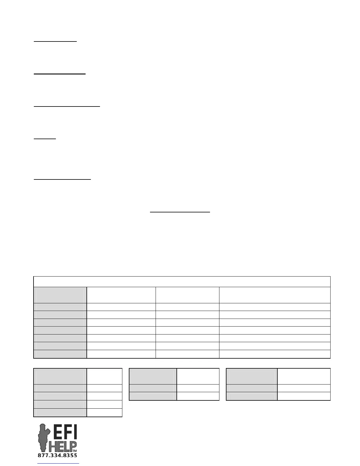
DIP Switch Settings
Your XIM™ unit is configurable for different engine applications. This is accomplished by using 8
DIP switches found inside the back cover of your unit. To access the DIP switches, simply take the lid
off by removing the 5 screws, being careful not to tear the gasket beneath the lid. Below you’ll find a
handy list of the current engine applications covered with your XIM™ unit and the switch settings that
are required for each. The “on” position is marked on the switches.
XIM™ DIP Switches
DIP Switch (1-4)
[0=OFF, 1=ON]
Ignition Strategy Crank Input
“Crank Ref. Angle (*BTDC)” setting
in C-Com XFI™ software
0 - 0 - 0 - 0 Crank Trigger 1/2/3/4X, 50* BTDC 50
1 - 0 - 0 - 0 OE Crank Trigger 1/2/3/4X, 1-10* BTDC Actual Crank Position (1-10) + 45
1 - 0 - 1 - 1 Ford Mod, 2 or 4 Valve 36-1 (1 tooth cam) 60
1 - 1 - 0 - 1 Ford Mod, 3 Valve 36-1 (5 tooth cam) 60
1 - 1 - 1 - 1 Chrysler Hemi 36-2-2 50
0 - 0 - 1 - 1 GM Gen 3 - LS1/LS6 24X (Special) 50
0 - 1 - 1 - 1 GM Gen 4 – LS2/LS7 60-2 49
DIP Switch (5-6)
[0=OFF, 1=ON]
# of
Cylinders
DIP Switch (7)
[0=OFF, 1=ON]
Operation
Mode
DIP Switch (8)
[0=OFF, 1=ON] Coil Layout
0 - 0 2 Cylinder 1 Stand Alone 1 Coil per Cylinder
1 - 0 4 Cylinder 0 CAN Enabled 0 Waste Spark
0 - 1 6 Cylinder
1 - 1 8 Cylinder
“CAN Enabled” allows XIM™ to
communicate with XFI™
“Waste Spark” – Each coil fires two
companion cylinders simultaneously.
 Loading...