Setup
Part
number
Aluminum housing &'ƑƑ &'ƑƑ &'ƑƑ
SUS housing
&'0ƑƑ &'0ƑƑ &'0ƑƑ
Center of measurement range 15mm 35mm PP
Measurement range ±5mm ±15mm PP
Light source Red laser Diode (wave length 655nm)
0D[RXWSXW:
Max. output: 1mW
※3
Laser
class
IEC/JIS
Spot size
※
1
P P P
Linearity RIF.S. RIF.S. RIF.S.
Repeatability
※
2
P P P
Sampling period VVVV AUTO
Temperature drift (typical value)
℃
of F.S.
℃
of F.S.
℃
of F.S.
Indicator Laser indicator: Green / Zero reset indicator: Red
Output indicator: Orange / Mode indicator: Red
Communication I/F 56+DOI'XSOH[0XOWLGURS,)LVQRWVXSSRUWHG
Power supply 9'&
Current consumption PA max.
Protection circuit Reverse connection protection, Over current protection
Protection category ,3LQFOXGLQJFRQQHFWLRQSDUW
Operating THPS+XPLG
~
℃
a5+ZLWKRXWIUHDVLQJRUFRQGHQVDWLRQ
Storage THPS+XPLG a
℃
/ 35 ~
5+
Ambient illuminance ,QFDQGHVFHQWODPSO[PD[
9ibration resistance a+]'RXEOHDPSOLWXGHPP;Y,Z for 2 hours
Shock resistance PPV
2
DSSUR[*;Y,Z 3 times each
Material
Case: Aluminum/SUS316L, Front lens: PPSU, Display: PET
Weight Aluminum case with M12 connector : $SSUR[JLQFOXGLQJ
PPFDEOHZLWKFRQQHFWRU
SUS case with M12 connector type : $SSUR[JLQFOXGLQJ
PPFDEOHZLWKFRQQHFWRU
$OXPLQXPFDVHZLWK0FRQQHFWRU $SSUR[J
686FDVHZLWK0FRQQHFWRU $SSUR[J
℃
, Sup
ply voltage: 9'& Sampling period: V Averaging: 64, Measuring distance: Center of the range, Testing
object: White ceramic
※
2
※
2 512 averaging time
※
/DVHU&ODVVW\SH0RGHO&'0&'&
●
●
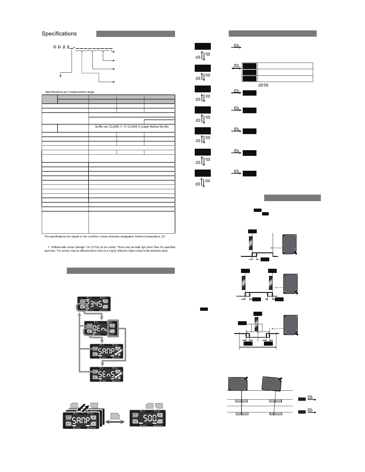
Part number legend
㻯㻌㻰㻌㻞㻌㻞㻌
䠻㻙㻌䠻㻌䠻㻌䠻㻌䠻㻌䠻㻌䠻㻌䠻㻌䠻㻌䠻
Measurement center distance (mm)
Output
Laser Class
Connector Ɣ M12 : M12
Ɣ C : M connector
Ɣ 9 : 9oltage 9
Ɣ A : Current 4mA
Ɣ : RS5
Ɣ Nul : Class 1
Ɣ 2 : Class 2
&DVH Ɣ Nul : Aluminum
Ɣ M : SUS316L
●Changingmode
Whileit's"Teachmode","Setupmode"or"Extensionmode",youcanchangethemode
to"Measurementmode"bypressing"ZERO/RUN"button.
Whileit's"Setupmode"or"Extensionmode",theLED"MANUAL"islit.
●
Changing parameters
YRXFDQFKRRVHDQGDGMXVWWKHSDUDPHWHUVE\SUHVVLQJDQGEXWWRQV
The mode will be changed to "Measurement mode" by pressing "ZERO/RUN" button.
㻿㻱㼀
䠉
䠇
䠉 䠇
㻯㼔㼍㼚㼓㼕㼚㼓
㼜㼍㼞㼍㼙㼑㼠㼑㼞
㻭㼐㼖㼡㼟㼠㼕㼚㼓
㼜㼍㼞㼍㼙㼑㼠㼑㼞
㻹㼑㼍㼟㼡㼞㼑㼙㼑㼚㼠
㻌㻌㻌㻌㻌㻌㻌㼙㼛㼐㼑
㼀㼑㼍㼏㼔㼕㼚㼓㻌㼙㼛㼐㼑
㻿㼑㼠㼡㼜㻌㼙㼛㼐㼑
㻱㼤㼠㼑㼚㼟㼕㼛㼚㻌㼙㼛㼐㼑
㻼㼞㼑㼟㼟㻌㼍㼠㻌㼍㻌㼠㼕㼙㼑
㼒㼛㼞㻌㻞㻌㼟㼑㼏㼛㼚㼐
Teach mode
mEnu
modE
FG52
nEAr
FAr
1pt
fG52
2pt
㻿㻱㼀
㻿㻱㼀
1 point Teaching
FGS2
2 point Teaching
tch
㻿㻱㼀
tch
㻿㻱㼀
tch
7HDFKLQJFXUUHQWSRVLWLRQ
7HDFKLQJFXUUHQWSRVLWLRQ
7HDFKLQJFXUUHQWSRVLWLRQ
㻿㻱㼀
To Setup mode
ٹ
Setup mode
ٹ
Teaching mode
ٹ
FGS2 threshold
CALn
㻿㻱㼀
tch
7HDFKLQJFXUUHQWSRVLWLRQ
ٹ
Calibration(Near end of range)
calf
㻿㻱㼀
tch
7HDFKLQJFXUUHQWSRVLWLRQ
ٹ
Calibration(Far end of the range)
ٹ
1HDUVLGHWKUHVKROG
ٹ
SRLQW7HDFKLQJ)DUVLGHWKUHVKROG
䠇
䞊
䠇
䞊
䠇
䞊
䠇
䞊
䠇
䞊
䠇
䞊
䠇
䞊
䠇
䞊
VZLWFKLQJ
Measurement mode
CD22 has 3 measurement mode. The mode is chosen by "Teach mode".
Output can be reversed by setting "Output polarity
Acti
Following output shows its ON/OFF status as "Light ON
L on
●1 point Teaching
Teaching is done at a position. When the measurement distance is closer than that position, the output
●2 point Teaching
●Calibration (Far end of the range/ Near end of range)
Teaching is done at 2 positions. While the measurement distance is between those positions, the output
The sensor can be calibrated by “Calibration” mode at both far and near end of the measurement range.
This feature is very useful especially when you can’t mount the sensor head parallel to the object surface.
●FGS2
Teaching is done at a position. When the measurement distance is closer than the distance set by +\V
toL
teresis
FAr
hYSt
㻻㻺
㻻㻲㻲
nEAr
hYSt
FGS2
hYSt
㻹㼑㼍㼟㼡㼞㼑㼙㼑㼚㼠㻌㼞㼍㼚㼓㼑
㻻㻺
㻻㻲㻲
hYSt
toL
FAr
hYSt
㻹㼑㼍㼟㼡㼞㼑㼙㼑㼚㼠㻌㼞㼍㼚㼓㼑
㻻㻺
㻻㻲㻲
Position of the target
PP䠄Near end of the range䠅
PP䠄Far end of 㼠㼔㼑㻌㼞㼍㼚㼓㼑䠅
PP䠄Reference distance䠅
㼙㼑㼍㼟㼡㼞㼑㼙㼑㼚㼠㻌㼞㼑㼟㼡㼘㼠䠖
㻙㻡㻜㻚㻜㻜
㼙㼑㼍㼟㼡㼞㼑㼙㼑㼚㼠㻌㼞㼑㼟㼡㼘㼠䠖
㻡㻜㻚㻜㻜
㼙㼑㼍㼟㼡㼞㼑㼙㼑㼚㼠㻌㼞㼑㼟㼡㼘㼠䠖
㻙㻠㻥㻚㻤㻝
㼙㼑㼍㼟㼡㼞㼑㼙㼑㼚㼠㻌㼞㼑㼟㼡㼘㼠䠖
㻡㻜㻚㻝㻥
cALn
㻿㻱㼀
㻙㻡㻜㻚㻜㻜
cALF
㻿㻱㼀
㻡㻜㻚㻜㻜
([DPSOHRI&DOLEUDWLRQRI&'
●
Just calibrate the sensor by “Calibration” mode at far end and near end of the measurement range.
Then, you will get calibrated result if the sensor head is tilted.
A䠅Calibration condition at the factory B䠅When the sensor is mounted tilted
".
".
will be ON.
will be ON.
"from the position that Teaching is done, the output will be ON. It works as FGS sensor.
Ramco Innovations
800
280-6933 www.optex-ramco.com nsales
ramcoi.comn
 Loading...