any obligations on the part of manufacture.
)RUPRUHLQIRUPDWLRQTXHVWLRQVDQGFRPPHQWVUHJDUGLQJ
6SHFLILFDWLRQVDQGHTXLSPHQWDUHVXEMHFWWRFKDQJHZLWKRXW
products, please contact us below.
Attention: Not to be Used for Personnel Protection.
Never use these products as sensing devices for personnel protection. Doing so could
lead to serious injury or death. These sensors do not include the VHOIFKHFNLQJ redundant
circuitry necessary to allow their use in personnel safety applications. A sensor failure or
PDOIXQFWLRQFDQFDXVHHLWKHUDQHQHUJL]HGRUGHHQHUJL]HGVHQVR routputcondition.
Please consult our distributors about safety products which meet 26+A, ANSI and IEC
standards for personnel protection.
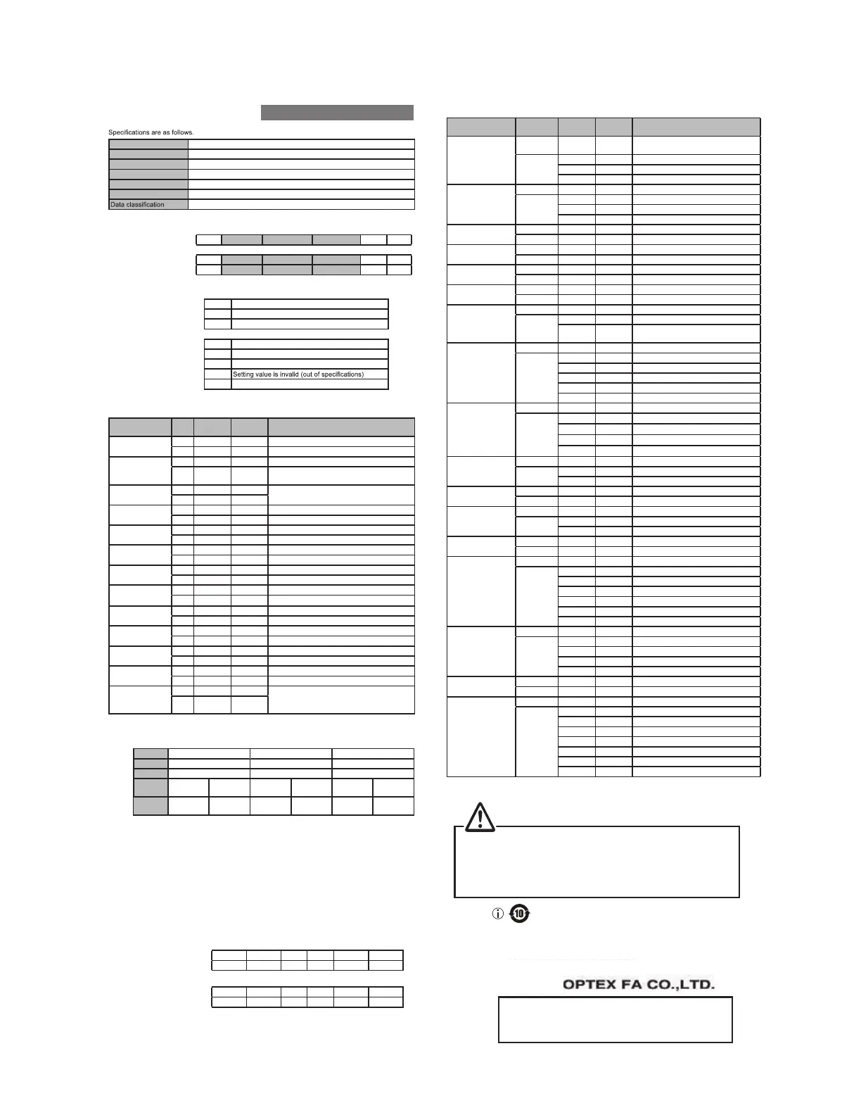
Communication
Communication method 56+DOI'XSOH[0XOWLGURS,)LVQRWVXSSRUWHG
Transmission code Binary
Data length ELW
Stop length 1bit
Parity check Nil
Baud rate (bps)
NNNN1NNNNNNNN0
67;(7;
Ŷ'DWD)RUPDW
Transmission data : 67; COMMAND DATA1 DATA2 (7; BCC
Incoming data : 67; $&. RESPONSE1 RESPONSE2 (7; BCC
Incoming data (error) : 67; 1$. ERROR CODE + (7; BCC
67; +(7; + $&. +1$. +%&& ;25RIYDOXHVKDWFKHG
Basic commands : &+ Individual function commands
:+ Writing the setting
5+ Reading out setting
Error code table : + Address is invalid
+ BCC value is invalid
+ Invalid command is issued except "C", "W", "R"
+
+ Setting value is invalid (out of range)
Ŷ&+SDUDPHWHUWDEOH
Command Type DATA1
(upper)
DATA2
(lower)
Description
Reading out
Measurement value
Write %K K
Read Upper data Lower data Response in 2 bytes
※
1
Reading out Output
status
Write %K K
Read K
Output
status
ELW 21
ELW WKHVWDWXVKDVEHHQUHDG
Writing the setting
Write $K K
Write the setting into EEPROM.
PVEHUHTXLUHGXQWLOWKHODVHUSRZHUVWDEOH
Read K K
Teaching FGS2
Write 11h K
Read K K
Teaching near side
point
Write 11h K
Read K K
Teaching far side
point
Write 11h K
Read K K
Laser ON
Write $K K
Read K K
Laser OFF
Write $K K
Read K K
Execute Zero reset
Write A1h K
Read K K
Release Zero reset
Write A1h K
Read K K
([HFXWH.H\ORFN
Write A1h K
Read K K
5HOHDVH.H\ORFN
Write A1h K
Read K K
Initializing
Write K K
Initialize all parameters except communication
speed and UHERRt. The communication won't
worrk while initializing.
Read K K
0HDVXUHPHQWDQGVHWWLQJYDOXHDUHGHDFULEHGDVVLJQHGKH[DGHFLPDO
Model &'ƑƑ &'ƑƑ &'ƑƑ
Range ±5mm ±15mm PP
Unit P P P
Data
+H[
(&K K FA24h '&K (&K K
Data
(Decimal)
ŶWriting Data
Writing is done as following proceedure.
1. Read out setting
Execute Command "R" (Reading out setting) on the target parameter.
Set "Address" at "DATA1" and "DATA2".
2. Write setting
Execute Command "W" (Writing the setting) on the target parameter.
Writing data is done to the address set at "1. Read setting".
Example: Setting "Sampling period" to "AUTO"
1. Read out "Sampling period"
Transmission command : 67;K R (52h) K K (7;K BCC (14h)
Incoming data : 67;K $&.K K K (7;K BCC K)
2. Write the setting
Transmission command : 67;K :K K K (7;K BCC (53h)
Incoming data : 67;K $&.K K K (7;K BCC K)
,QFRPLQJGDWDRIFRPPDQG:WULWLQJWKHVHWWLQJZLOOEHKDQGK
Ŷ6HWWLQJSDUDPHWHUWDEOH
Setting Address/
Parameter
DATA1
(upper)
DATA2
(lower)
Description
Model type
Address K K
Return center value of measurement
range (only for checking model type)
Parameter
K )K 15mm type
K 23h PPW\SH
K 64h PPW\SH
Measurement mode
Address K K
Parameter
K K 2 point Teaching
K K 1 point Teaching
K K FGS2 Teaching
Near side threshold
Address 41h K
Parameter Upper data Lower data
Far side threshold
Address 41h K
Parameter Upper data Lower data
FGS2 threshold
Address 41h K
Parameter Upper data Lower data
FGS2 hysteresis
Address 41h K
Parameter Upper data Lower data
Output polarity
Address K K
Parameter
K K Light ON: ON when exceeds the threshold
K K
Dark ON: ON when less than the
threshold
Sampling period
Address K K
Parameter
K K V
K K V
K K V
K K V
K K AUTO
Averaging number
Address K $K
Parameter
K K Once
K K WLPHV
K K 64 times
K K 512 times
Alarm setting
Address K &K
Parameter
K K Clamp
K K +ROG
$ODUP+ROGDQG
Clamp
Address 41h K
Parameter Upper data Lower data
Display setting
Address K (K
Parameter
K K ON
K K OFF
+\VWHUHVLV
Address 41h K
Parameter Upper data Lower data
Measurement point
Address
K K
Parameter
K K 0$;0D[LPXPGLVWDQFH
K K
K K
K K
K K
K K
Threshold
Address K 12h
Parameter
K K Base : Lowest level
K K /HYHOORZHUOHYHO
K K /HYHOPLGGOHOHYHO
K K /HYHOXSSHUOHYHO
Zero reset value
Address 41h 12h
Parameter Upper data Lower data
Sensitivity
Address K 14h
Parameter
K K AUTO
K K 1 : Minimum sensitivity
K K 2
K K 3
K K 4
K K 5
K K 6 : Maximum sensitivity
([HFXWHWKHFRPPDQG55HDGRXWEHIRUHH[HFXWLQJFRPPDQGW" (Write).
Pt1 : Closest point from sensor side
Pt5 : 5th point from sensor side
Pt4 : 4th point from sensor side
Pt3 : 3rd point from sensor side
Pt2 : 2nd point from sensor side
Manufactured and sold by :
䊻
KWWSZZZRSWH[IDFRPURKVBFQ
Ramco Innovations
800
280-6933 www.optex-ramco.com nsales
ramcoi.comn
 Loading...