13
ENGLISH
Even through operating with a 24 Volt insulating system,
the ball BOXes are equipped on the inside with a faston
device in order to be connected to the electrical
grounding system.
There are BOXes for all kinds of games. See the section
on "ARTICLE CODES".
On the CONTROL-BALL board, a red light indicates:
the connection to the MICRO32 is okay
the unit is not connected to the
MICRO32
the CONTROL-BALL is either broken or
has no power supply.
The CONTROL-BALL may also be connected to simple
ball containers in which the withdrawal of the tray turns on
a micro-switch. In this case, the game start takes place
automatically when the tray is taken out.
If you wish that automatic START to be a club operation,
you can regulate it before or within one minute of the tray's
extraction by pushing the START-CLUB button and then
the button for the table involved.
The two micro-switch wires are connected in the same
way as the two BOX wires.
flashing light:
light always on:
light off:
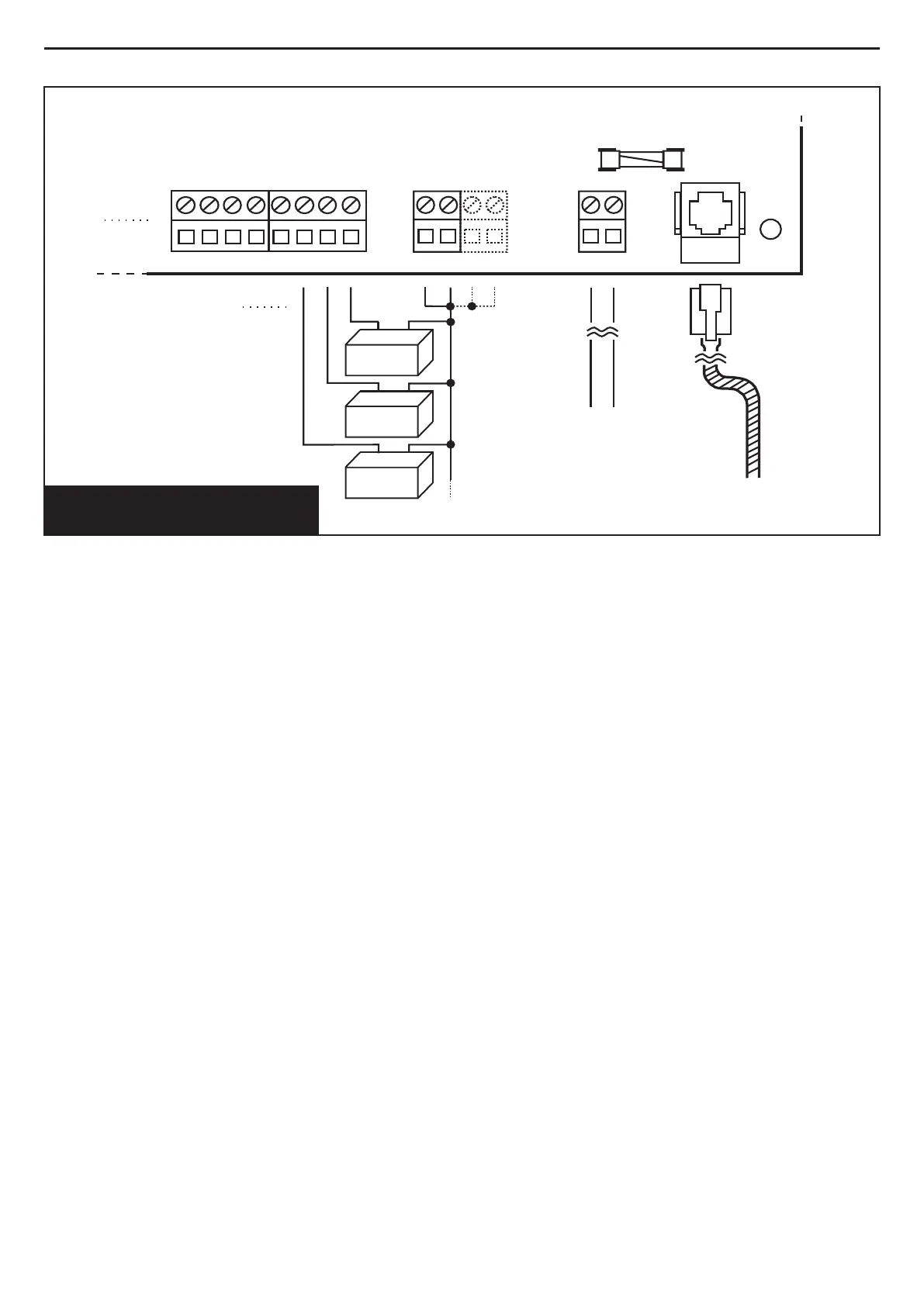
FIG. 2 CONTROL-BALL
CONNECTIONS
230V
SERIAL
LINE
COMMON-BOX
CONTROL-BALL BOARD
BOXes
1mm
2
min.
Wire section
CONTROL-BALL
POWER-SUPPLY
CONNECTION
TO THE MICRO32
230 Vac 250mA
2
1
3
12345678
FUSE T 315mA 250 Vac
NOTES
Containers of CONTROL-LAMP and CONTROL-BALL are
in material Class: IEC 650.
If the wiring is not fitted with protection from short circuits
and indirect contacts for all equipment, this must be
carried out by the client.
The Manufacturer declines all responsibility if the
equipment is tampered with.